Battery level reading using ADC pin from nRF chip shows significant fluctuation

Hi everyone,

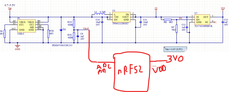
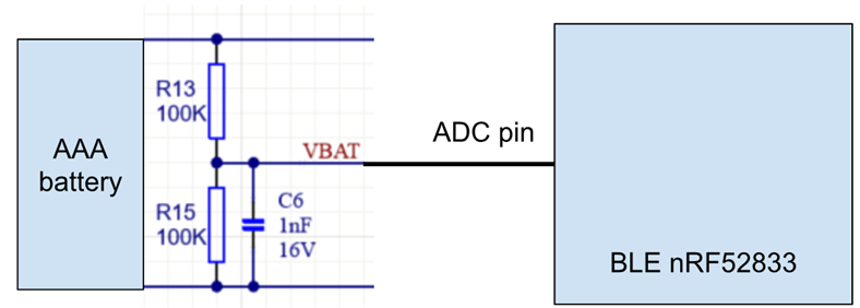
We're reading BAT level by reading data from ADC pin and the setup diagram is shown below. 

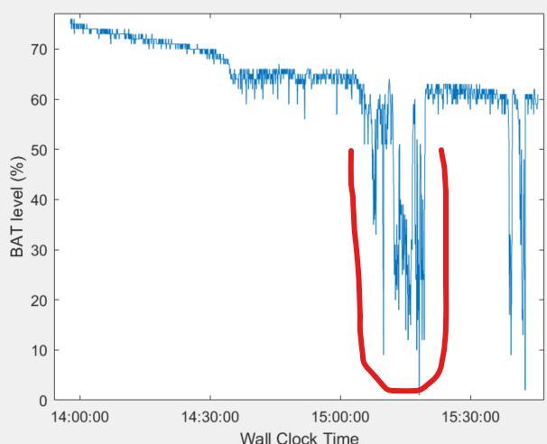
We tested our device at hospital, and we observed significant fluctuation highlighted in red regarding its BAT level. For example, it went from 65% to 20%, then jumped to 60% again. 

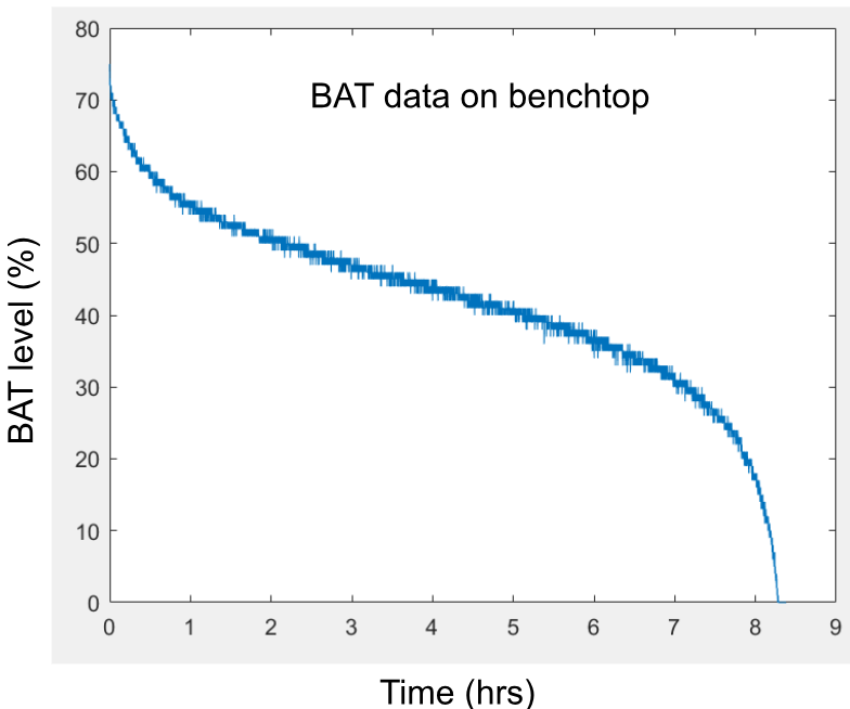
We then took the device and battery back to the office and tried to reproduce the issue on benchtop. However, we couldn't reproduce it. In contrast, the following is what we got, and it worked as expected.

Our hypothesis is that it could be due to the impedance mismatch between ADC input pin and the output of voltage divider. However, based on our calculation, the input impedance of the voltage divider is equivalent to R13//R15 (50kOhm) while the input impedance of ADC pin is more than 1MOhm. This would not cause the impedance mismatch. 

I greatly appreciate if anyone has any suggestions for this issue. Thanks.

Parents
  • Hi Tai,

    I dare not claim to be an expert, but I have been assigned the case, and will try to help.

    This behavior is indeed abnormal. The SAADC on the nRF52 series doesn't have any limitation that would explain that.

    Could you please elaborate what you did in the bench test? I notice that the discharge curve in the field test isn't similar to that in the bench test, assuming that the drain is constant in both scenarios.

    Is it possible that the device underwent any special mode, or was put under abnormal environmental condition during the time with the measurement dip?
    For example, extreme EM noises requiring multiple retries, keeping the radio on for longer, increasing the current draw.

    Is this observed multiple times or just once, and with one particular unit, or multiple units?

    Hieu

  • Hi Hieu. 

    Could you please elaborate what you did in the bench test? I notice that the discharge curve in the field test isn't similar to that in the bench test, assuming that the drain is constant in both scenarios.

    I used exact hardware device and battery used in hospital. I basically turned the device on, connected to our mobile application, then let it run till the battery is fully depleted. I left the device on my desk, which is normal working environment in the office. 

    Side note: The first discharge curve was only 1.5 hr long measurement while the second one conducted on bench test was 8 hr long. 

    Is it possible that the device underwent any special mode, or was put under abnormal environmental condition during the time with the measurement dip?

    It was running under normal mode. For environmental condition at hospital, it has many medical equipment and there is presence of 2.4 GHz frequency component emitted by this equipment. In other words, it is pretty noisy, and we observed several BLE disconnects due to that before.

    However, for this case I did check the RSSI values recorded in our application. It looked normal.

    Is this observed multiple times or just once, and with one particular unit, or multiple units?

    It happened for us twice in different hospitals. For another case, we put a branch new battery, the HW device showed low BAT right away and BLE disconnect happened after a couple minutes.

  • "AAA Battery" - 1 AAA battery or more than 1 battery? If only 1 battery then how does the AAA 1.5V provide the nRF VDD, ie could you share the regulator schematic for the VDD supply? Perhaps also share the calculation for battery % and include the number of readings used, or show the battery voltage instead of the battery %.

  • We used 1 AAA battery (1.5V) and a boost-buck converter to have the voltage of 3V to power the device. The average life span of battery is about 11.5 hrs.

Reply Children
  • There are so many tests (200 +) done before without any issue with the discharge BAT curve. It recently happened, so I'm very confused.

    Btw, I developed this based on the way to measure BAT level as following:

  • Several issues here:

    • the resistors are not actually required as the  AAA battery voltage is always less than VDD so can be measured directly.
    • the battery will phantom power the ADC pin before the regulator first starts up and supplies VDD; this can create reset problems
    • a series resistor of  high value to the ADC pin can reduce the phantom power risk but will not eliminate the phantom power; most notably on a battery change
    • battery percentage measurement is really only reliable with a known load and temperature
    • shortened battery life is nearly always caused by some unexpected scenario leading to unexpected wakeups (no sleep) or leaving peripherals on when they should be off
    • a low-Iq boost is preferable to a buck-boost as the battery voltage will never be high enough to require buck mode - the regulator will always be in boost mode to meet the minimum nRF52 VDD (say 1.7V)

    Worth searching the devzone for "phantom power" and "back-drive" for more discussions.

    nrf52832-io-problem

    battery-monitoring-circuit

  • Thanks  ! I'll take a look at it and we can have more discussion.

  • Summary: "We tested our device at hospital" - result battery issues; tested on bench, no battery issues

    Environment: Hospital has high density WiFi and BLE devices all competing for bandwidth; on the bench not so

    Consequence: Hospital continuous advertising attempting to connect initially or reconnect on a lost connection; bench probably only require a single advert on start or subsequent link loss to re-establish connection

    Algorithm: Sensible BLE devices implement a gradual backoff on advertising, such that if a connection is not established within (say) 2 seconds the advertising rate is reduced; perhaps from 20 or 50 times per second to (say) 2 times per second. Silly BLE devices continue to hammer out advertising packets at a high rate even when it is clear a connection is taking ages to re-establish, and this drains the battery quickly. A low or drained battery will exhibit distorted capacity measurements.

    The test: on the bench ensure there are no devices which will connect with the device; observe battery profile to see if similar to hospital site.

    The fix: (Should this indeed be the case) Implement a gradual advertising backoff algorithm

    ble-advertising-power-management

  • Thanks  ! 

    the battery will phantom power the ADC pin before the regulator first starts up and supplies VDD; this can create reset problems

    The following is my power circuit

    Is that really a potential problem here? I'll measure the voltage going into ADC pin and VDD to see which one comes first. In the case ADC pin comes first, will a higher resistor value in R13 help mitigate this issue? Or any other ways to improve it with the current setup?

    Reading your answers in some posts, my understanding is that having TX pin or ADC pin in my case high while the nRF52 is not being powered on potentially causes some issues for nRF52 reset. However, I'm still unsure the root cause for my issue with sudden significant fluctuation BAT level. Is that because of phantom power that leads to some unexpected nRF52 working behavior?

    You mentioned about advertising packet on nRF52. From my understanding, it's potential for nRF52 to draw more current due to a connection establishment effort in a noisy environment, leading to shorten BAT life. I noticed there was no issue with establishing a BLE connection as no issue reported about this so far. However, I'll use BLE sniffer to confirm this in the hospital next time. Please correct me if I'm wrong. 

    Another thought of having shorten BAT life when measuring in a noisy environment is that to maintain BLE connection, the device and tablet need to exchange data packet frequently based on the define connection interval. In the noisy environment, high chance that these data packets need to be retransmitted many times, which leads to a high BAT drain.

Related