MISO line mimics the MOSI line in SPIM configuration sdk 17.1.0

Hi,

When I looked at the SPI lines using the oscilloscope, I saw that the MISO line had the same signal as the MOSI line. As you can see from the image, basically SPI configuration works properly. Before message transfer CS pin goes low, and after that, the MOSI line works. I can read message that I sent using the oscilloscope.
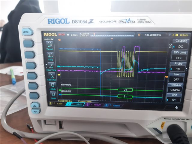
What can be the problem with the MISO line signal reflecting the MOSI line signal? The SPI config stage CPOL = 0, CPAH = 1, I am using a 2 MHz clock signal. Thanks for your help.

  • Thanks for your reply  . This is the file that I created for ADS1299_nRF.

    #ifndef ADS1299_NRF_H
    #define ADS1299_NRF_H
    
    #include <stdbool.h>
    #include <stdint.h>
    
    #define PIN_SCK   NRF_GPIO_PIN_MAP(0, 14)  // SCLK, confirm this
    #define PIN_MOSI  NRF_GPIO_PIN_MAP(0, 13)  // MOSI, confirm this
    #define PIN_MISO  NRF_GPIO_PIN_MAP(0, 12)  // MISO, confirm this
    #define CS_PIN    NRF_GPIO_PIN_MAP(0, 31)  // CS, confirm this (previously P0.4)
    #define PIN_DRDY  NRF_GPIO_PIN_MAP(0, 7)   // DRDY, confirm this
    #define RESET_PIN NRF_GPIO_PIN_MAP(0, 11)
    
    // ADS1299 Commands
    #define COMMAND_WAKEUP  0x02
    #define COMMAND_STANDBY 0x04
    #define COMMAND_RESET   0x06
    #define COMMAND_START   0x08
    #define COMMAND_STOP    0x0A
    #define COMMAND_RDATAC  0x10
    #define COMMAND_SDATAC  0x11
    #define COMMAND_RDATA   0x12
    #define COMMAND_RREG    0x20
    #define COMMAND_WREG    0x40
    
    // ADS1299 Register Addresses
    #define ID          0x00
    #define CONFIG1     0x01
    #define CONFIG2     0x02
    #define CONFIG3     0x03
    #define LOFF        0x04
    #define CH1SET      0x05
    #define CH2SET      0x06
    #define CH3SET      0x07
    #define CH4SET      0x08
    #define CH5SET      0x09
    #define CH6SET      0x0A
    #define CH7SET      0x0B
    #define CH8SET      0x0C
    #define BIAS_SENSP  0x0D
    #define BIAS_SENSN  0x0E
    #define LOFF_SENSP  0x0F
    #define LOFF_SENSN  0x10
    #define LOFF_FLIP   0x11
    #define LOFF_STATP  0x12
    #define LOFF_STATN  0x13
    #define GPIO        0x14
    #define MISC1       0x15
    #define MISC2       0x16
    #define CONFIG4     0x17
    
    typedef struct {
        uint16_t lead_off_positive;
        uint16_t lead_off_negative;
        bool gpio_0;
        bool gpio_1;
        bool gpio_2;
        bool gpio_3;
        int32_t channel_0;
        int32_t channel_1;
        int32_t channel_2;
        int32_t channel_3;
        int32_t channel_4;
        int32_t channel_5;
        int32_t channel_6;
        int32_t channel_7;
    } ADS1299_data_t;
    
    bool ADS1299_init(void);
    bool ADS1299_send_command(uint8_t command);
    bool ADS1299_read_register(uint8_t address, uint8_t *value);
    bool ADS1299_write_register(uint8_t address, uint8_t value);
    bool ADS1299_send_start(void);
    bool ADS1299_send_read_continuous(void);
    bool ADS1299_send_reset(void);
    bool ADS1299_send_sdatac(void);
    bool ADS1299_receive_data(void);
    bool ADS1299_poll_new_data(ADS1299_data_t *data);
    void poll_dready(void);
    void send_new_available_data(void);
    ADS1299_data_t ADS1299_convert_data(void);
    void spi_init(void);
    bool spi_transfer_byte_v2(uint8_t tx, uint8_t *rx);
    uint8_t spi_transfer_byte(uint8_t tx);
    
    /*********NEW FUNCTIONS NOT USED************/
    
    void mySPI_int(void);
    void PowerUp_ADS(void);
    uint8_t RREG_ADS(uint8_t address);
    void Recognize_ADS(void);
    void Reset_ADS(void);
    void SendADSCommand(uint8_t data, uint32_t delaytime);
    
    #endif // ADS1299_NRF_H

  • I see the pins listed in the project on the nRF52840 DK are shared with other functions, in particular BUTTON2 and U8 input are connected to MISO P0.12. This may not load the pin significantly, but best to test MISO with an uncommitted pin on the nRF52840 (if not already done so).

    I'll try to find time to test the code on a similar device.

  • Some bugs to fix. transfer_byte only reads a single byte which is fine if just sending a commend with no response but not ok if reading a response as the response is in the 2nd 3rd byte, not the first:

        *value = spi_transfer_byte(0x00);
    
    Perhaps instead:
        uint8_t rx[3];
    ...
        SPIM2->RXD.MAXCNT = 3;
    ...
        NRF_LOG_INFO("SPI TX: 0x%02x, RX: 0x%02x", tx, rx[2]);
        return rx[2];

  • Thanks for your reply  . Did you find any other bugs that needed fixing after your search?

  • I thinck here you were trying to read a response, but this reads the 3rd byte, better to just use the fix above:

        spi_transfer_byte(opcode1);
        spi_transfer_byte(0x00);
        *value = spi_transfer_byte(0x00);
    

    maybe like this:

        *value = spi_transfer_byte(command);

    unless you are trying to insert a delay between command byte and data; better to get it working at 500KHz and then optimise

Related