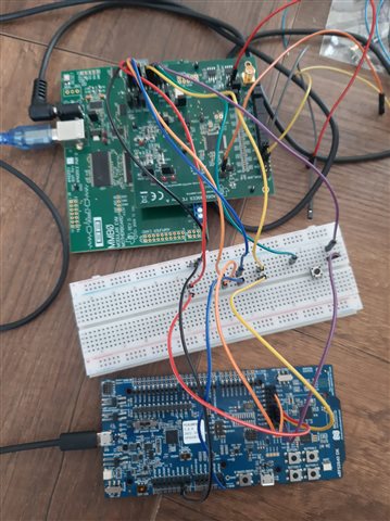
MISO line mimics the MOSI line in SPIM configuration sdk 17.1.0

Hi,

When I looked at the SPI lines using the oscilloscope, I saw that the MISO line had the same signal as the MOSI line. As you can see from the image, basically SPI configuration works properly. Before message transfer CS pin goes low, and after that, the MOSI line works. I can read message that I sent using the oscilloscope.
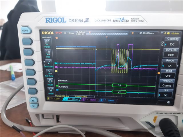
What can be the problem with the MISO line signal reflecting the MOSI line signal? The SPI config stage CPOL = 0, CPAH = 1, I am using a 2 MHz clock signal. Thanks for your help.

  • The code (you shared) contains none of the suggestions we made then? If it does have the suggestions, without having sight of the changes we are blind as to providing any feedback. One other suggestion, if I may, is that all measurements for SCK, /CS and MOSI should be as close to the ADS1299 pins as possible, not at the nRF52.

  • The clock frequency is 2 MHz. These are the latest configuration results that I got from the logic analyser. 

    This is my connection actually, I am getting the result in the middle of the two pins between ADS1299 and nRF52840DK. 

    According to your suggestions, this is my code's latest state. 

    #include "ADS1299_nRF.h"
    #include <nrf.h>
    #include <nrf_log.h>
    #include <nrf_log_ctrl.h>
    #include <nrf_log_default_backends.h>
    #include <nrf_gpio.h>
    #include <nrf_delay.h>
    #include "ads1299_delay.h"
    
    // Enable polling mode for DRDY
    #define POLL_DREADY
    
    #define SPIM2 NRF_SPIM2
    
    bool new_data_available = false;
    uint8_t rx_buffer[27], tx_buffer[8];
    uint8_t sample_number = 0;
    static uint8_t regData[24]; // Mirror of ADS1299 registers
    
    /** @brief SPI interface initialization. Accurate timing use HFCLK clock */
    void spi_init(void) {
        // Start HFCLK source for accurate timing
        NRF_CLOCK->TASKS_HFCLKSTART = 1;
        while (NRF_CLOCK->EVENTS_HFCLKSTARTED == 0);
        NRF_CLOCK->EVENTS_HFCLKSTARTED = 0;
        
        // Disable SPIM to configure it
        SPIM2->ENABLE = (SPIM_ENABLE_ENABLE_Disabled << SPIM_ENABLE_ENABLE_Pos);
        
        NRF_P0->OUTSET = (1 << CS_PIN);
    
        // Set High-drive pin mode for SPI
        nrf_gpio_cfg(PIN_SCK,  NRF_GPIO_PIN_DIR_OUTPUT, NRF_GPIO_PIN_INPUT_CONNECT, NRF_GPIO_PIN_NOPULL, NRF_GPIO_PIN_H0H1, NRF_GPIO_PIN_NOSENSE);
        nrf_gpio_cfg(PIN_MOSI, NRF_GPIO_PIN_DIR_OUTPUT, NRF_GPIO_PIN_INPUT_CONNECT, NRF_GPIO_PIN_NOPULL, NRF_GPIO_PIN_H0H1, NRF_GPIO_PIN_NOSENSE);
        nrf_gpio_cfg(CS_PIN,   NRF_GPIO_PIN_DIR_OUTPUT, NRF_GPIO_PIN_INPUT_CONNECT, NRF_GPIO_PIN_NOPULL, NRF_GPIO_PIN_H0H1, NRF_GPIO_PIN_NOSENSE);
        nrf_gpio_cfg(PIN_MISO, NRF_GPIO_PIN_DIR_INPUT,  NRF_GPIO_PIN_INPUT_CONNECT, NRF_GPIO_PIN_NOPULL, NRF_GPIO_PIN_H0H1, NRF_GPIO_PIN_NOSENSE);
    
        NRF_P0->OUTSET = (1 << CS_PIN);
    
        // Configure SPIM2 pins
        SPIM2->PSEL.SCK = PIN_SCK;
        SPIM2->PSEL.MOSI = PIN_MOSI;
        SPIM2->PSEL.MISO = PIN_MISO;
    
        SPIM2->FREQUENCY = SPIM_FREQUENCY_FREQUENCY_M2; // 2 MHz (t_CLK = 500 ns)
        
        SPIM2->ORC = 0xFF;
    
        // ADS1299 set Data mode: clock polarity = 0, clock phase = 1
        SPIM2->CONFIG = (SPIM_CONFIG_CPOL_ActiveHigh << SPIM_CONFIG_CPOL_Pos) |  // CPOL = 0
                        (SPIM_CONFIG_CPHA_Trailing << SPIM_CONFIG_CPHA_Pos) |     // CPHA = 1
                        (SPIM_CONFIG_ORDER_MsbFirst << SPIM_CONFIG_ORDER_Pos);
        
        SPIM2->EVENTS_END = 0;
        SPIM2->EVENTS_ENDTX = 0;
        SPIM2->EVENTS_ENDRX = 0;
        
        SPIM2->INTENCLR = 0xFFFFFFFFUL;
        SPIM2->INTENSET = 0x040;
        
        SPIM2->ENABLE = (SPIM_ENABLE_ENABLE_Enabled << SPIM_ENABLE_ENABLE_Pos);
    }
    
    static void spi_uninit(void) {
        SPIM2->ENABLE = (SPIM_ENABLE_ENABLE_Disabled << SPIM_ENABLE_ENABLE_Pos);
        nrf_gpio_cfg_input(PIN_SCK, NRF_GPIO_PIN_NOPULL);
        nrf_gpio_cfg_input(PIN_MOSI, NRF_GPIO_PIN_NOPULL);
        nrf_gpio_cfg_input(PIN_MISO, NRF_GPIO_PIN_NOPULL);
    }
    
    uint8_t spi_transfer_byte(uint8_t tx) {
        uint8_t rx;
        memset(&rx, 0, sizeof(rx));
        if (!(SPIM2->ENABLE & SPIM_ENABLE_ENABLE_Msk)) {
            SPIM2->ENABLE = (SPIM_ENABLE_ENABLE_Enabled << SPIM_ENABLE_ENABLE_Pos);
        }
        // Clear events before starting
        SPIM2->EVENTS_ENDTX = 0;
        SPIM2->EVENTS_ENDRX = 0;
        SPIM2->EVENTS_END = 0;
        
        // Configure buffers
        SPIM2->TXD.PTR = (uint32_t)&tx;
        SPIM2->TXD.MAXCNT = 1;
        SPIM2->RXD.PTR = (uint32_t)&rx;
        SPIM2->RXD.MAXCNT = 1;
        
        // Start transaction
        SPIM2->TASKS_START = 1;
        
        // Wait for transaction to complete
        while (!SPIM2->EVENTS_ENDTX);
        while (!SPIM2->EVENTS_ENDRX);
        while (!(SPIM2->EVENTS_END));
    
        nrf_delay_us(2); // t_CSH: Minimum 1 µs hold time after SCLK falling edge
        
        NRF_LOG_INFO("SPI TX: 0x%02x, RX: 0x%02x", tx, rx);
        return rx;
    }
    
    bool spi_transfer_bytes(const uint8_t *tx, uint8_t *rx, size_t len) {
        if (!(SPIM2->ENABLE & SPIM_ENABLE_ENABLE_Msk)) {
            SPIM2->ENABLE = (SPIM_ENABLE_ENABLE_Enabled << SPIM_ENABLE_ENABLE_Pos);
        }
        
        static uint8_t dummy_tx = 0xFF;
        static uint8_t dummy_rx;
    
        SPIM2->EVENTS_END = 0;
        SPIM2->TXD.PTR = (uint32_t)(tx ? tx : &dummy_tx);
        SPIM2->TXD.MAXCNT = len;
        SPIM2->RXD.PTR = (uint32_t)(rx ? rx : &dummy_rx);
        SPIM2->RXD.MAXCNT = len;
    
        SPIM2->TASKS_START = 1;
        while (!SPIM2->EVENTS_END);
        SPIM2->ENABLE = SPIM_ENABLE_ENABLE_Disabled; // Disable SPIM to allow pull-up to take effect
        return true;
    }
    
    void ADS1299_pwr_up_seq(void)
    {
        nrf_delay_ms(40);
        nrf_gpio_cfg(RESET_PIN, NRF_GPIO_PIN_DIR_OUTPUT, NRF_GPIO_PIN_INPUT_DISCONNECT, NRF_GPIO_PIN_NOPULL, NRF_GPIO_PIN_H0H1, NRF_GPIO_PIN_NOSENSE);
        nrf_gpio_pin_clear(RESET_PIN);
        nrf_delay_us(2);
        nrf_gpio_pin_set(RESET_PIN);
        nrf_delay_us(10);
    }
    
    bool ADS1299_init(void) {
        // Recommended power-up sequence for ADS1299
        
        NRF_LOG_INFO("Initializing ADS1299");
        ADS1299_pwr_up_seq();
        nrf_delay_ms(1000);
        ADS1299_pwr_up_seq();
        
        spi_init();
    
        nrf_gpio_cfg_input(PIN_DRDY, NRF_GPIO_PIN_NOPULL);
    
        NRF_LOG_INFO("SPI init success");
    #ifdef POLL_DREADY
        NRF_LOG_INFO("DRDY polling enabled");
    #else
        NRF_LOG_INFO("DRDY interrupt not implemented");
    #endif
        return true;
    }
    
    void poll_dready(void) {
    #ifdef POLL_DREADY
        NRF_LOG_INFO("Polling DRDY, state: %d", nrf_gpio_pin_read(PIN_DRDY));
        if (nrf_gpio_pin_read(PIN_DRDY) == 0) {
            NRF_LOG_INFO("DRDY low, receiving data");
            ADS1299_receive_data();
            send_new_available_data();
        }
    #endif
    }
    
    bool ADS1299_write_register(uint8_t address, uint8_t value) {
    
        uint8_t cmd[] = {
            (uint8_t)(address | COMMAND_WREG),
            0x00, // Write 1 register
            value
        };
    
        nrf_gpio_pin_clear(CS_PIN);
        nrf_delay_us(6); // t_CSSC: Delay from CS low to first SCLK (min 6 ns, use 50 ns for safety)
        spi_transfer_bytes(cmd, NULL, sizeof(cmd));
        nrf_delay_us(1); // t_CSH: Delay from last SCLK to CS high (min 1 µs)
        nrf_gpio_pin_set(CS_PIN);
        nrf_delay_us(1); // t_CSH hold time after CS high
    
        regData[address] = value;
        return true;
    }
    
    bool ADS1299_read_register(uint8_t address, uint8_t *value) {
        //uint8_t tx_buf[] = {
        //    (uint8_t)(address | COMMAND_RREG),
        //    0x00,  // Read 1 register
        //    0x00   // Dummy byte for response
        //};
        //uint8_t rx_buf[3] = {0};
        
        uint8_t opcode1 = (address | 0x20);
        nrf_gpio_pin_clear(CS_PIN);
        spi_transfer_byte(opcode1);
        spi_transfer_byte(0x00);
        *value = spi_transfer_byte(0x00);
        nrf_gpio_pin_set(CS_PIN);
        nrf_delay_us(1); // t_CSH hold time after CS high
    
        regData[address] = *value;
        return true;
    }
    
    bool ADS1299_send_command(uint8_t command) {
        uint8_t dummy;
        nrf_gpio_pin_clear(CS_PIN);
        spi_transfer_byte(command);
        nrf_gpio_pin_set(CS_PIN);
        nrf_delay_us(1); // t_CSH hold time after CS high
        return true;
    }
    
    bool ADS1299_send_start(void) {
        bool result = ADS1299_send_command(COMMAND_START);    
        return result;
    }
    
    bool ADS1299_send_read_continuous(void) {
        bool result = ADS1299_send_command(COMMAND_RDATAC);
        nrf_delay_us(3); // Allow RDATAC to settle
        return result;
    }
    
    bool ADS1299_send_reset(void) {
        bool result = ADS1299_send_command(COMMAND_RESET);
        NRF_LOG_INFO("Reset command sent, result: %d", result);
        return result;
    }
    
    bool ADS1299_send_sdatac(void) {
        bool result = ADS1299_send_command(COMMAND_SDATAC);
        NRF_LOG_INFO("Stop read continuously command sent, result: %d", result);
        return result;
    }
    
    bool ADS1299_receive_data(void) {
        new_data_available = false;
        if (!spi_transfer_bytes(NULL, rx_buffer, 27)) {
            NRF_LOG_ERROR("Failed to receive data");
            return false;
        }
        new_data_available = true;
        NRF_LOG_INFO("Data received, triggering send_new_available_data");
        return true;
    }
    
    bool ADS1299_poll_new_data(ADS1299_data_t *data) {
        if (new_data_available) {
            new_data_available = false;
            *data = ADS1299_convert_data();
            return true;
        }
        return false;
    }
    
    static inline int32_t buffer_to_channel(uint8_t id) {
        int32_t value = (rx_buffer[3 + id * 3] << 16) | (rx_buffer[4 + id * 3] << 8) | rx_buffer[5 + id * 3];
        if (value & 0x00800000) {
            value |= 0xFF000000;
        } else {
            value &= 0x00FFFFFF;
        }
        return value;
    }
    
    ADS1299_data_t ADS1299_convert_data(void) {
        ADS1299_data_t data;
        data.lead_off_positive = rx_buffer[0] << 4;
        data.lead_off_positive |= (rx_buffer[1] & 0b11110000) >> 4;
        data.lead_off_negative = rx_buffer[1] << 4;
        data.lead_off_negative |= (rx_buffer[2] & 0b11110000) >> 4;
        data.gpio_0 = rx_buffer[2] & 0b00001000;
        data.gpio_1 = rx_buffer[2] & 0b00000100;
        data.gpio_2 = rx_buffer[2] & 0b00000010;
        data.gpio_3 = rx_buffer[2] & 0b00000001;
        data.channel_0 = buffer_to_channel(0);
        data.channel_1 = buffer_to_channel(1);
        data.channel_2 = buffer_to_channel(2);
        data.channel_3 = buffer_to_channel(3);
        data.channel_4 = buffer_to_channel(4);
        data.channel_5 = buffer_to_channel(5);
        data.channel_6 = buffer_to_channel(6);
        data.channel_7 = buffer_to_channel(7);
        return data;
    }
    
    void send_new_available_data(void) {
        if (new_data_available) {
            new_data_available = false;
            NRF_LOG_INFO("Sample: %d", sample_number++);
            for (uint8_t i = 0; i < 27; i++) {
                NRF_LOG_INFO("Byte %d: 0x%02x", i, rx_buffer[i]);
            }
        }
    }


    And this code part is my main.

    #include <nrf.h>
    #include <nrf_log.h>
    #include <nrf_log_ctrl.h>
    #include <nrf_log_default_backends.h>
    #include "ADS1299_nRF.h"
    #include "nrf_delay.h"
    #include "nrf_gpio.h"
    
    #define LED_PIN NRF_GPIO_PIN_MAP(0,13)  // LED1 on nRF52840 DK
    
    int main(void) {
        NRF_LOG_INIT(NULL);
        NRF_LOG_DEFAULT_BACKENDS_INIT();
    
        nrf_gpio_cfg_output(LED_PIN);
        nrf_gpio_pin_clear(LED_PIN);
    
        NRF_LOG_INFO("Starting ADS1299 initialization");
    
        if (!ADS1299_init()) 
        {
            NRF_LOG_ERROR("ADS1299 init failed");
            while (1) {
                nrf_gpio_pin_toggle(LED_PIN);
                NRF_LOG_FLUSH();
                nrf_delay_ms(200);
            }
        }
    
        if(!ADS1299_send_sdatac())
        {
            NRF_LOG_INFO("ADS1299 SDATAC operation failed.");
        }
        else
        {
            NRF_LOG_INFO("SDATAC succesfully");
        }
    
        uint8_t id;
        ADS1299_read_register(ID,&id);
        if(id == 0x3E)
        {
            NRF_LOG_INFO("ADS1299 communication succes");
        }
        else
        {
            NRF_LOG_INFO("ADS1299 communication fail");
        }
    
    }

  • Remove the MMB0 base board, power the ADS board from the DK directly.

    I don't remember if the MMB0 was neutral or not by default - but you want control to be entirely on the Nordic chip.

    The connectors should be on a 2.54mm raster - we used a prototyping board for our experimental setup that was hand soldered rather quickly. No, I don't have a schematic here.

  • Thanks for your quick reply  . Can it be that the problem with the MMBO board is not recognising the nRF chip as a master? Anyway, do you see any misconfiguration in the traces that I share?

    Hi   I have removed the MMBO baseboard and powered the ADS from the DK. However, I am getting the same result: the ADS is not responding. 

  • Tried to compile, but need specific ADS1299_nrf.h which you are using

Related