
Hey everyone. I am having an issue reading the WHO_AM_I register from the stm lsm6dsv16x.
I am using the spi1 configuration as shown in the academy classes. I have very short cables.
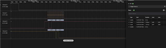
The issue I get is. I am constantly reading 0x60, but I should be reading 0x70.
I also see people have similar issues from this stm link
community.st.com/.../810200
I tested in multiple configurations in Mode 0 and 3 ( supported only by lsm6dsv16x). But for some reason I could never get the frist bit correct. I am following similar code you guys have for the spi read on the academy course, but still get 0x60.
the boards I am using is the lsm6dsv16x sparkfun breakout board( I made sure it is configured for spi) and the nrf52840dk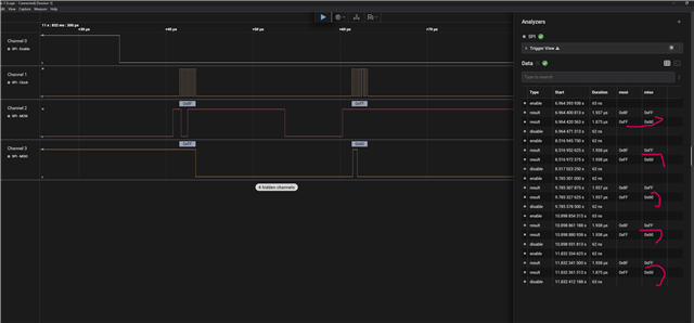
&spi2 {
    compatible = "nordic,nrf-spim";
    status = "okay";
    cs-gpios = <&gpio0 30 GPIO_ACTIVE_LOW>;
    pinctrl-0     = <&spi2_default>;
    pinctrl-1     = <&spi2_sleep>;
    pinctrl-names = "default", "sleep";

    lsm6dsv16x: lsm6dsv16x@0 {
        status = "okay";
        compatible = "zephyr,custom-lsm6dsv16x";
        reg = <0>;
        spi-cpol;
        spi-cpha;
        spi-max-frequency = <4000000>;
        int1-gpios = <&gpio1 9  (GPIO_PULL_DOWN | GPIO_ACTIVE_HIGH)>;
        int2-gpios = <&gpio0 3  (GPIO_PULL_DOWN | GPIO_ACTIVE_HIGH)>;
    };
};
&{/aliases} {
    imu0 = &lsm6dsv16x;   /* flip to &imu_icm to build with the other driver */


};

&pinctrl {
    i2c0_default: i2c0_default {
        group1 { psels = <NRF_PSEL(TWIM_SCL, 0, 27)>,
                         <NRF_PSEL(TWIM_SDA, 0, 5)>; };
    };
    i2c0_sleep: i2c0_sleep {
        group1 { psels = <NRF_PSEL(TWIM_SCL, 0, 27)>,
                         <NRF_PSEL(TWIM_SDA, 0, 5)>;
                 low-power-enable; };
    };

    spi2_default: spi2_default {
        group1 { psels = <NRF_PSEL(SPIM_SCK, 0, 28)>,
                         <NRF_PSEL(SPIM_MOSI, 0, 29)>,
                         <NRF_PSEL(SPIM_MISO, 0, 31)>;
                         };
    };
    spi2_sleep: spi2_sleep {
        group1 { psels = <NRF_PSEL(SPIM_SCK, 0, 28)>,
                         <NRF_PSEL(SPIM_MOSI, 0, 29)>,
                         <NRF_PSEL(SPIM_MISO, 0, 31)>;
                 low-power-enable;
                };
    };
};

int32_t platform_read(void *handle, uint8_t reg, uint8_t *bufp, uint16_t len)
{
    const struct lsm6dsv16x_config *cfg = handle;

    uint8_t tx_buffer = reg | 0x80;  // Set MSB to indicate read
    uint8_t rx_buffer[len + 1];      // Temporary buffer to receive extra byte

    struct spi_buf tx_bufs[] = {
        { .buf = &tx_buffer, .len = 1 },
    };
    struct spi_buf rx_bufs[] = {
        { .buf = rx_buffer, .len = len + 1 },
    };

    struct spi_buf_set tx_set = { .buffers = tx_bufs, .count = 1 };
    struct spi_buf_set rx_set = { .buffers = rx_bufs, .count = 1 };

    int ret = spi_transceive_dt(&cfg->spi, &tx_set, &rx_set);
    if (ret < 0) {
        return ret;
    }

    memcpy(bufp, &rx_buffer[1], len);  // Skip dummy byte
    return 0;
}
