Power profiler Kit II for NRF54L15

Hi,

When i want to connect my Power profiler kit II to my laptop, it first blinks GREEN.
After i connect to it using the power profiler app, it goes:               RED -> AMP (Ampere meter) mode | BLUE -> SMU (source meter) mode
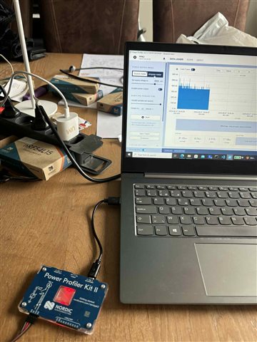
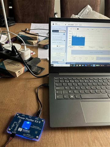
I believe this behavior that we want.


But then, for my nRLF54L15 board, which some of them are programmed to be reflectors and some initiators, i want to know HOW TO CONNECT this device to my ppk2 successfully. I think it should be with these pins "VDDM CURRENT MEASURE" as shown below:
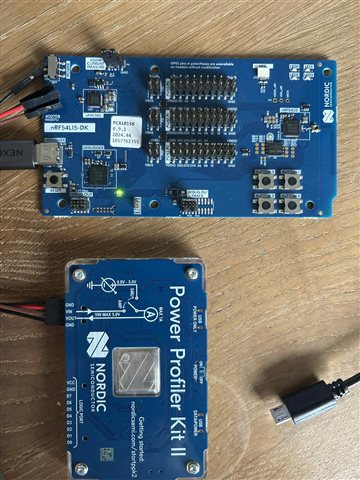
Although, i tried connecting 3 of the 4 pins from the ppk2 with these pins, but after i detach the black  (probably to short the 2 VIN VOUT pins) thingy, i get this:
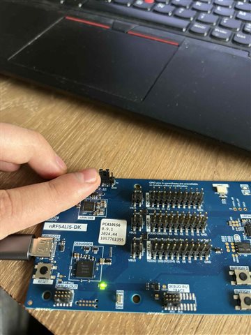


Also, i had an issue that now 1 board doesn't connect at all with my computer, after doing this. Why is this? I had it before, but i put the black thing on another way, and i pressed "Reset" and then i reconnected. But now it doesn't do that, and it still doesn't want to work anymore...

Can someone help me with this?

Kind regards,

Nick De Leenheer

Parents
  • Hello,

    Although, i tried connecting 3 of the 4 pins from the ppk2 with these pins, but after i detach the black  (probably to short the 2 VIN VOUT pins) thingy, i get this

    You get what?

    Looking at your picture in the middle (of your original post), assuming that the 4 pins are still connected to the PPK in the same order as they are in the picture, you want to take the bottom three ones (order: Red, Brown, Black), and connect them to the DK's P6 (the one where you removed the small black piece), and put red in the left one, brown in the middle one, and black in the right one (marked GND).

    Then, in the Power Profiler application on your computer, make sure that "enable output power" is checked, like it is in your second screenshot. Then hit start, and you should be able to see your live current measurement.

    Best regards,

    Edvin

Reply
  • Hello,

    Although, i tried connecting 3 of the 4 pins from the ppk2 with these pins, but after i detach the black  (probably to short the 2 VIN VOUT pins) thingy, i get this

    You get what?

    Looking at your picture in the middle (of your original post), assuming that the 4 pins are still connected to the PPK in the same order as they are in the picture, you want to take the bottom three ones (order: Red, Brown, Black), and connect them to the DK's P6 (the one where you removed the small black piece), and put red in the left one, brown in the middle one, and black in the right one (marked GND).

    Then, in the Power Profiler application on your computer, make sure that "enable output power" is checked, like it is in your second screenshot. Then hit start, and you should be able to see your live current measurement.

    Best regards,

    Edvin

Children
No Data
Related