I'm trying to implement DFU over USB through Serial Recovery, for a custom board using a nRF52840, following the nRF Connect SDK Intermediate Lesson 9: Exercise 4 – DFU over USB - Nordic Developer Academy.
My goal would be to update the firmware by connecting a USB Type-C cable to my receptor on my PCB and to my computer hosting the new firmware.
I'm using VS Code as my editor with the nRF Connect Extension, the nRF connect SDK v3.0.0 and the toolchain version v3.0.2.
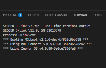
So far, i managed to have two build images (one for the main app and one for MCUboot) and flash them inside my PCB custom board with sysbuild. Using an external button connected to my nRF52840 on my Printed Circuit Board (PCB), when i reboot the board (and hold the external button pressed down), i manage to launch the MCUboot image (i can see that it worked because a LED is configured to be turned ON when MCUboot is in Serial Recovery mode, again following Lesson 9 Exercice 1: Exercise 1 - DFU over UART - Nordic Developer Academy).
My problem comes when i try to connect a USB cable from my USB Type-C connector on my PCB to my computer (when the board is running MCUboot in Serial recovery mode). Nothing is recognised by my computer host (no COM port visible and no audio sound from connecting something in the commputer USB port).
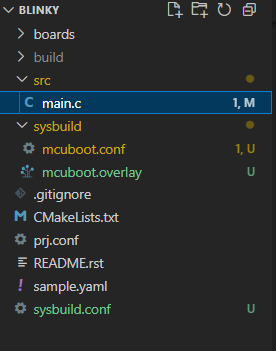
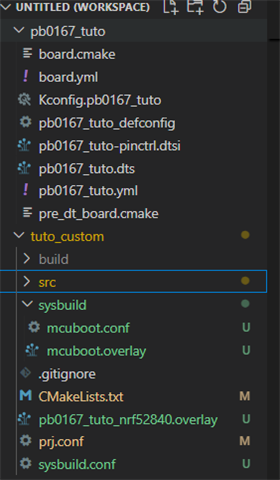
Here is my workspace:
 .
.
pb0167_tuto is my board file and tuto_custom is the file holding my application (with sysbuild file for MCUboot). Here are the following content of the files on my workspace:
sysbuild.conf:
 .
.
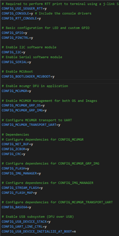
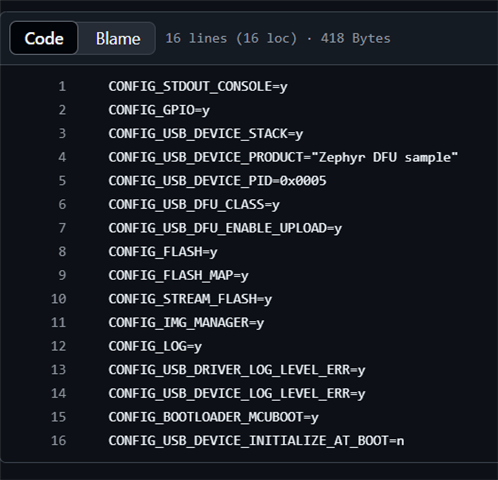
prj.conf:
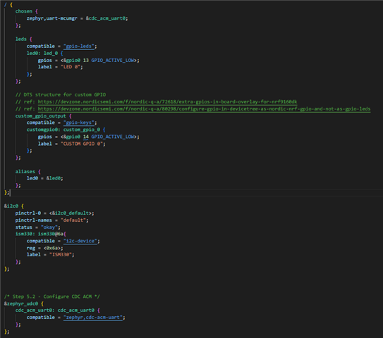
pb0167_tuto_nrf52840.overlay:
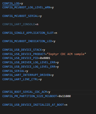
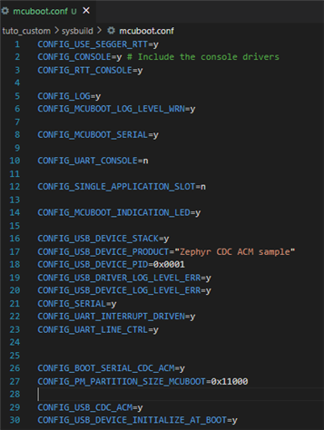
mcuboot.conf:
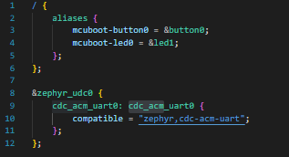
mcuboot.overlay:
 .
.
Since i'm using a custom board, i also configured my proper dts file for my board file (and thus shared by my main app build image and MCUboot build image):
The associated pinctrl.dtsi for the board file as the following content:
All of the above, when using nRF Connect extensino can be build and results as the following output from VS Code:
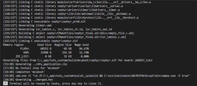 .
.
My Questions are: If MCUboot seems to be working on my board, why my computer does not recognise the USB on my custom PCB when i connect a USB type-C connector from my PCB to my computer ? Why I cannot see a COM port appearing on my host computer ? Does everything presented hereabove, in my implementation and files, seems right to perform Serial Recovery for DFU over USB using AuTerm (recommanded by nRF in Exercise 4 – DFU over USB) ?
Many thanks in advance for the persons reading this.


 .
. .
.  ?
?