About Tx current consumption in nRF54L

Hi,

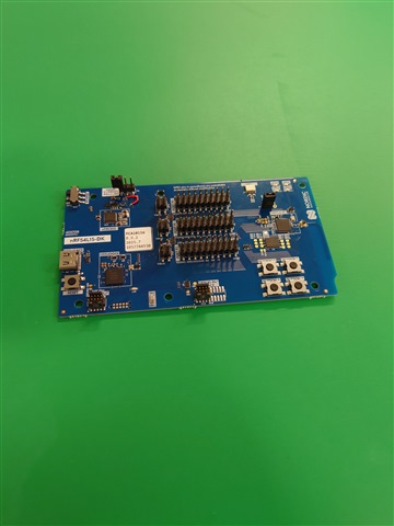
I am currently developing an nRF54L15 module.

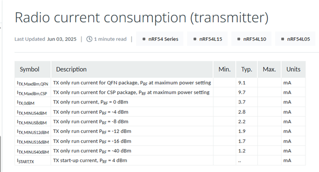
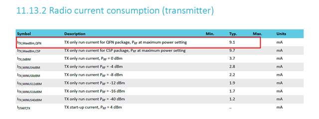
During the evaluation, I measured the Tx current consumption and got a result that was 2mA higher than the value listed in the data sheet.

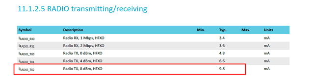
The current consumption being confirmed is IRADIO_TX2 below.

Under the IRADIO_RX0 conditions, values ​​equivalent to those in the data sheet were measured.

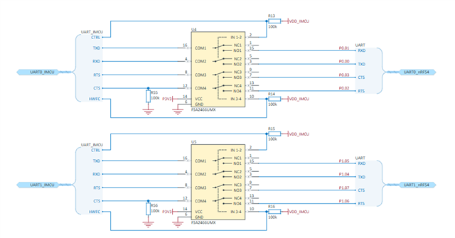
To identify the cause, I modified it with an nRF54l dk and tried to measure at 3.0 V to see if there was a difference.
However, since it was impossible to measure at 3.0 V, I checked at 1.8 V to see if there was a current difference between the evaluation board and the module under development.


There was no difference in the results.
It was about 21mA.
When powered at 1.8V, the current consumption is the same as that of the nRF54L15, so I believe there will be no problems with the module under development.

The conditions for measurement at 1.8V were as follows:

Frequency: 2440MHz

Regulator: DC/DC

Tx Power: 8dBm

Modulation: BLE 1M

Firmware used:radio test sample code

sdk:v2.9.1


Measurements were also taken under the same conditions at 3.0V.


The current consumption of the nRF54ldk was measured using the diagram at the following URL as a reference.
docs.nordicsemi.com/.../measure_ampmeter.html

Please investigate what the problem is.

best regards,

Hiroki

Parents
  • Hello,

    Regarding this ''Could you tell us the environment in which you measured IRADIO_TX2'' query, did you get the screenshot from previous version of product documentation? Our latest specification looks like this 

    Radio current consumption (transmitter)

    The nRF54L15 DK is using QFN, the spec 9.1 mA is from characterization on internal RF boards instead of DKs.

    Test env: 25°C,3V, DCDC mode on (that you need to set in the config file), HFXO, BLE1M, TX OP +8dBm.   

    We can also test on DKs but in terms of price that is not efficient. 

  • Hi, Kazi

    Here Set up the DK is the description of setup.

    I have checked, but do I need to remove the following parts?
    Do I need to remove U4 and U5 physically, not via a pattern?

    The nRF54L15 DK is using QFN, the spec 9.1 mA is from characterization on internal RF boards instead of DKs.

    The above was verified using Nordic's own board so we cannot verify it, right?

    Test env: 25°C,3V, DCDC mode on (that you need to set in the config file), HFXO, BLE1M, TX OP +8dBm.   

    We can also test on DKs but in terms of price that is not efficient. 

    The module we are developing is different from the results in the datasheet, so we would like to first check if there are any differences with Nordic's board.

    When measured with Nordic's dedicated board, it is 9.1mA, but the Tx 8dBm listed in the data sheet below is 9.8mA. Why is there a difference?

    best regards,

    Hiroki

Reply
  • Hi, Kazi

    Here Set up the DK is the description of setup.

    I have checked, but do I need to remove the following parts?
    Do I need to remove U4 and U5 physically, not via a pattern?

    The nRF54L15 DK is using QFN, the spec 9.1 mA is from characterization on internal RF boards instead of DKs.

    The above was verified using Nordic's own board so we cannot verify it, right?

    Test env: 25°C,3V, DCDC mode on (that you need to set in the config file), HFXO, BLE1M, TX OP +8dBm.   

    We can also test on DKs but in terms of price that is not efficient. 

    The module we are developing is different from the results in the datasheet, so we would like to first check if there are any differences with Nordic's board.

    When measured with Nordic's dedicated board, it is 9.1mA, but the Tx 8dBm listed in the data sheet below is 9.8mA. Why is there a difference?

    best regards,

    Hiroki

Children
No Data
Related