About Tx current consumption in nRF54L

Hi,

I am currently developing an nRF54L15 module.

During the evaluation, I measured the Tx current consumption and got a result that was 2mA higher than the value listed in the data sheet.

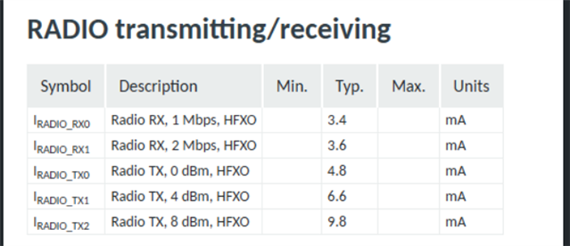
The current consumption being confirmed is IRADIO_TX2 below.

Under the IRADIO_RX0 conditions, values ​​equivalent to those in the data sheet were measured.

To identify the cause, I modified it with an nRF54l dk and tried to measure at 3.0 V to see if there was a difference.
However, since it was impossible to measure at 3.0 V, I checked at 1.8 V to see if there was a current difference between the evaluation board and the module under development.


There was no difference in the results.
It was about 21mA.
When powered at 1.8V, the current consumption is the same as that of the nRF54L15, so I believe there will be no problems with the module under development.

The conditions for measurement at 1.8V were as follows:

Frequency: 2440MHz

Regulator: DC/DC

Tx Power: 8dBm

Modulation: BLE 1M

Firmware used:radio test sample code

sdk:v2.9.1


Measurements were also taken under the same conditions at 3.0V.


The current consumption of the nRF54ldk was measured using the diagram at the following URL as a reference.
docs.nordicsemi.com/.../measure_ampmeter.html

Please investigate what the problem is.

best regards,

Hiroki

Parents
  • Hello Hiroki,

    The current consumption change is a physical effect of the mismatch, not an active adjustment by the SoC itself. When impedance mismatches between the power amplifier (PA) and the antenna, most of the transmitted power is reflected back into the power amplifier rather than being radiated. This causes PA to draw more current, sometimes significantly more. This is not unique for nRF54L15 but is a general characteristic of RF systems when antenna matching network is designed for 50ohm impedance.

    Regarding your initial query, Following is the reply from relevant team.

    '' In chapter Current consumption:

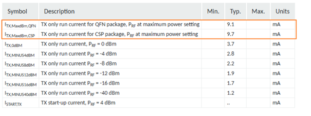
    In chapter RADIO Electrical specification:

    The discrepancy of the current consumption values in those two places is expected.

    Because in RADIO Electrical spec table, the ITX,MaxdBm,QFN ITX,MaxdBm,CSP values are the calculated radio standalone current consumption.

    While in Current consumption chapter, the current was measured from system level, see test conditions description, the IRADIO_TX2 is 9.8 mA as it takes clock, CPU, cache, RAM current consumption into account.''

Reply
  • Hello Hiroki,

    The current consumption change is a physical effect of the mismatch, not an active adjustment by the SoC itself. When impedance mismatches between the power amplifier (PA) and the antenna, most of the transmitted power is reflected back into the power amplifier rather than being radiated. This causes PA to draw more current, sometimes significantly more. This is not unique for nRF54L15 but is a general characteristic of RF systems when antenna matching network is designed for 50ohm impedance.

    Regarding your initial query, Following is the reply from relevant team.

    '' In chapter Current consumption:

    In chapter RADIO Electrical specification:

    The discrepancy of the current consumption values in those two places is expected.

    Because in RADIO Electrical spec table, the ITX,MaxdBm,QFN ITX,MaxdBm,CSP values are the calculated radio standalone current consumption.

    While in Current consumption chapter, the current was measured from system level, see test conditions description, the IRADIO_TX2 is 9.8 mA as it takes clock, CPU, cache, RAM current consumption into account.''

Children
No Data
Related