Hi,
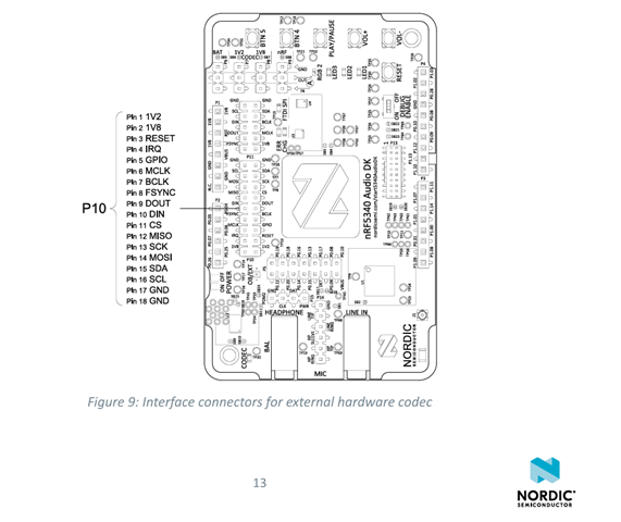
I am currently trying to integrate a digital microphone with the I2S peripheral of nRF5340 audio DK. I am accessing the P10 header of the nRF board for the particular I2S pins:
1) Pin 6-MCLK
2) Pin 7-BCLK
3) Pin 8-FSYNC
4) Pin 9-DOUT
5) Pin 10-DIN
The problem that I am facing is that I am not able to initialise the P10 header in my overlay file and I assume that is the reason I am not getting any readings.
Can I get some assitance regarding how to initialise the P10 headers in order to establish I2S communication between the microphone and nRF5340 audio DK.
Below is a code which defines the overlay file for a device which uses I2S interface.
In this code, I2S is being initialised on P5 of the nRF board.
I want to establish I2S communicaton similarly with P10 header of the board.
&i2c1 {
status = "okay";
clock-frequency = <I2C_BITRATE_STANDARD>;
pinctrl-0 = <&i2c1_default>;
pinctrl-1 = <&i2c1_sleep>;
pinctrl-names = "default", "sleep";

tlv320aic: tlv320aic@18 {
compatible = "i2c-device";
status = "okay";
reg = <0x18>;
};
};

&i2s0 {
status = "okay";
pinctrl-0 = <&i2s0_default_alt>;
pinctrl-1 = <&i2s0_sleep_alt>;
pinctrl-names = "default", "sleep";
compatible = "nordic,nrf-i2s";
#address-cells = <1>;
#size-cells = <0>;
reg = <0x28000 0x1000>;
interrupts = <40 NRF_DEFAULT_IRQ_PRIORITY>;
};

&pinctrl {
i2c1_default: i2c1_default {
group1 {
psels = <NRF_PSEL(TWIM_SDA, 1, 2)>,
<NRF_PSEL(TWIM_SCL, 1, 3)>;
bias-pull-up;
};
};

i2c1_sleep: i2c1_sleep {
group1 {
psels = <NRF_PSEL(TWIM_SDA, 1, 2)>,
<NRF_PSEL(TWIM_SCL, 1, 3)>;
low-power-enable;
};
};

i2s0_default_alt: i2s0_default_alt {
group1 {
psels = <NRF_PSEL(I2S_SCK_M, 0, 14)>, // I2S BCLK on P0.14
<NRF_PSEL(I2S_LRCK_M, 0, 16)>,
<NRF_PSEL(I2S_SDOUT, 0, 15)>,
<NRF_PSEL(I2S_MCK,0, 12)>;
// bias-pull-up;
};
};
i2s0_sleep_alt: i2s0_sleep_alt {
group1 {
psels = <NRF_PSEL(I2S_SCK_M, 0, 14)>,
<NRF_PSEL(I2S_LRCK_M, 0, 16)>,
<NRF_PSEL(I2S_SDOUT, 0, 15)>,
<NRF_PSEL(I2S_MCK,0, 12)>;
low-power-enable;
};
};
};