How to deal with the power accuracy issue with nRF7002 and nRF7000?

Hi Nordic,

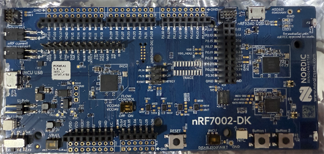
I test with nRF7002-DK and IC mark on nRF7002 is below:

N7002
QFAAB0
2252AA


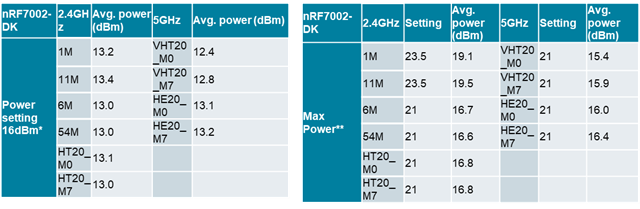
Here is my test data, showing about a 3dB discrepancy between power setting and measurement power (left sheet). When I set a higher power, I also get a higher measurement power (right sheet). Therefore, I would like to ask if there is a calibration mechanism to ensure that when I set 16dBm, the measurement power is also 16dBm, or how to deal with the power accuracy issue? I believe that a difference of less than 0.5dB between the power setting and measurement power is reasonable. Otherwise, there will be issues with Tx certification due to mismatching between power setting and measurement power.


Parents Reply Children
  • I use Litepoint IQ-MW to test average and peak power. I can share my test result: www.dropbox.com/.../Wi-Fi-test.xlsx

    We have always used average power for testing, and with other solutions, there is no issue of power not matching the settings. If there is a mismatch of around +-1dB, you can adjust the power by setting Tx_gain through commands.

  • You provide command is about "compensate" not "calibrate". Is there a command about "calibrate"? 

  • I use different fw setting to test Tx power. One is CONFIG_NRF70_ANT_GAIN_2G=CONFIG_NRF70_ANT_GAIN_5G=0, and another is CONFIG_NRF70_ANT_GAIN_2G=CONFIG_NRF70_ANT_GAIN_5G=6. I find there is still a gap form setting and measure bt 3.5~1.5dB. In 3590RER004_DRAFT - EN 300 328 V2.2.2.pdf p9, the setting is wifi_radio_test_tx_power 20 and we get 15~19 dBm Max Burst EIRP. So, is Nordic willing to admit that a 3dB difference between set power and measured power is normal and does not require adjustment?

    Thanks.

     3590RER004_DRAFT - EN 300 328 V2.2.2.pdf

        Kconfig=0 Kconfig=6   Kconfig=0 Kconfig=6
    nRF7002-DK 2.4GHz Avg. power (dBm) Avg. power (dBm) 5GHz Avg. power (dBm) Avg. power (dBm)
    Power setting 16dBm 1M 13.2 13.6 VHT20_M0 12.4 13.5
    11M 13.4 13.7 VHT20_M7 12.8 14.0
    6M 13 13.6 HE20_M0 13.1 14.3
    54M 13 13.6 HE20_M7 13.2 14.5
    HT20_M0 13.1 13.5      
    HT20_M7 13 13.5      
  • Hi, 

    Ketil is out of the office, so I take this case.

    It is not clear if you have compensated for the PCB loss in these measurements. Can you clarify?

    1. For the nRF7002-DK, we have typically measured ~1.5dB PCB loss in the 2.4GHz band and ~3dB PCB loss in the 5G band.

    2. Note that all the power numbers in the Product Specifications are at the nRF70 chip RF pin and not at the PCB antenna port - Just FYI (and hence need proper compensation for PCB loss and any other connector, cables losses, etc) to get accurate results.

    3. Assuming the TX power numbers they are quoting at the antenna connector and not compensated for PCB loss, adding the nRF7002DK PCB loss, brings them close to the PS numbers.

    -Amanda H.

Related