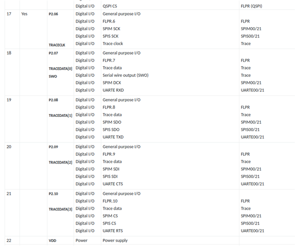
Background - We are laying out a new board, upgrading to the nRF54, and wanted to use p2.02 and p2.03 as serial UART lines because p1.04 and p1.05 were planned to be used as analog inputs. We could do another board spin to swap these ADCs with the UART, and move some other pins, but I wanted to make sure that will work before we make more hardware changes.
Current state - I have written a device tree overlay for the nRF54L15 (moved from a nRF52840) to set up our peripherals. While testing UART, I noticed there was garbage on the TXD and nothing I was sending from my computer is registering or echoing back on the device. I've tried other microcontrollers and other cables. The waveform looks decent, a little ringing, but upon closer inspection there seems to be a bit of clock stretching and data clobbering. My scope can't decode the data, either.
The TXD signal line occasionally destabilizes after the device stops transmitting data. I think this is correct because it's supposed to be an open drain, and only RXD gets a pull-up biasing, right?
So my questions -
- Is this current setup possible with pinmuxing?
- Are there external physical line requirements?
- Is the better solution to swap back to the default uart20 pins and move other pins around?
- Could I put the pins on another device like uart21 or uart30?
- Are there other unknowns about p2 pins and their ability to mux with various I/O?
- Should the device be configured for UART Async or UART Interrupt driven? I've tried both and they appear the same.
Relevant schematic: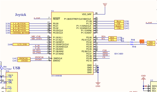
nRF54_BL54L15.overlay
/*
 * Copyright (c) 2025 Alex Movitz
 *
 * SPDX-License-Identifier: N/A
 */

/ {
	model = "Smart Dental Probe";
	compatible = "nordic,nrf54l15dk_nrf54l15-cpuapp";

	zephyr,user {
		io-channels = <&adc 0>, <&adc 1>;
	};

	// Remove nodes added in dev kit dtsi
    /delete-node/ aliases;
	/delete-node/ leds;
    /delete-node/ pwmleds;

    aliases {
		watchdog0 = &wdt31;
        vibrator = &vibrator;
        buzzer = &buzzer;
		sw0 = &button0;
		sw1 = &button1;
		sw2 = &button2;
		sw3 = &button3;
		sw4 = &button4;
		joystick = &adc;
    };

	chosen {
	};

	output: out0 {
		compatible = "gpio-leds";
		status = "okay";

		vibrator: vibrator {
			gpios = <&gpio1 10 (GPIO_PULL_DOWN | GPIO_ACTIVE_HIGH)>;
			label = "VIBRATOR";
		};

		buzzer: buzzer {
			gpios = <&gpio1 9 (GPIO_PULL_DOWN | GPIO_ACTIVE_HIGH)>;
			label = "BUZZER";
		};
	};

    buttons: buttons {
        compatible = "gpio-keys";
        status = "okay";
		button_t_f: button_0 {
			gpios = <&gpio0 0 (GPIO_PULL_UP | GPIO_ACTIVE_LOW)>;
			label = "Top Front Button";
			zephyr,code = <INPUT_KEY_0>;
		};
		button_t_r: button_1 {
			gpios = <&gpio0 1 (GPIO_PULL_UP | GPIO_ACTIVE_LOW)>;
			label = "Top Rear Button";
			zephyr,code = <INPUT_KEY_1>;
		};
		button_b_f: button_2 {
			gpios = <&gpio0 2 (GPIO_PULL_UP | GPIO_ACTIVE_LOW)>;
			label = "Bottom Front Button";
			zephyr,code = <INPUT_KEY_0>;
		};
		button_b_r: button_3 {
			gpios = <&gpio0 3 (GPIO_PULL_UP | GPIO_ACTIVE_LOW)>;
			label = "Bottom Rear Button";
			zephyr,code = <INPUT_KEY_1>;
		};
		button4: button_c: button_4 {
			gpios = <&gpio0 4 (GPIO_PULL_UP | GPIO_ACTIVE_LOW)>;
			label = "Center Button";
			zephyr,code = <INPUT_KEY_2>;
		};
    };
};

&adc {
	#address-cells = <1>;
	#size-cells = <0>;
	label = "Joystick ADC";

	channel@0 {
		reg = <0>;
		zephyr,gain = "ADC_GAIN_1";
		zephyr,reference = "ADC_REF_INTERNAL";
		zephyr,acquisition-time = <ADC_ACQ_TIME_DEFAULT>;
		zephyr,input-positive = <NRF_SAADC_AIN0>; /* P1.04 */
		zephyr,resolution = <12>;
		zephyr,oversampling = <8>;
	};

	channel@1 {
		reg = <1>;
		zephyr,gain = "ADC_GAIN_1";
		zephyr,reference = "ADC_REF_INTERNAL";
		zephyr,acquisition-time = <ADC_ACQ_TIME_DEFAULT>;
		zephyr,input-positive = <NRF_SAADC_AIN1>; /* P1.05 */
		zephyr,resolution = <12>;
		zephyr,oversampling = <8>;
	};
};

&i2c21 {
	compatible = "nordic,nrf-twim";
	status = "okay";
	pinctrl-0 = <&i2c21_default>;
	pinctrl-1 = <&i2c21_sleep>;
	pinctrl-names = "default", "sleep";
	clock-frequency = <I2C_BITRATE_FAST>;

	lsm6ds3tr_c: lsm6ds3tr-c@6a {
		compatible = "st,lsm6dsl";
		reg = <0x6a>;
		irq-gpios = <&gpio1 6 GPIO_ACTIVE_HIGH>;
		status = "okay";
	};

    ssd1306@3c {
        compatible = "solomon,ssd1306fb";
        reg = <0x3c>;
        label = "SSD1306";
        height = <64>;
        width  = <128>;
        segment-offset  = <0>;
        page-offset     = <0>;
        display-offset  = <0>;
        multiplex-ratio = <63>;
        prechargep      = <0x22>;
        segment-remap;
        com-invdir;
        com-sequential;
		reset-gpios = <&gpio1 3 GPIO_ACTIVE_HIGH>;
		status = "okay";
    };
};

&gpio0 {
    status = "okay";
};

&gpio1 {
    status = "okay";
};

&gpio2 {
    status = "okay";
};

&uart20 {
	status = "okay";
	pinctrl-0 = < &uart20_default >;
	pinctrl-1 = < &uart20_sleep >;
	pinctrl-names = "default", "sleep";
	current-speed = < 115200 >;
	// endtx-stoptx-supported;
	// frame-timeout-supported;
	// /delete-property/ endtx-stoptx-supported;
	// /delete-property/ frame-timeout-supported;
};

&uart30 {
	status = "disabled";
};


// Disable NFC
&uicr {
	nfct-pins-as-gpios;
};

// SD Card
&spi00 {
	status = "okay";
	cs-gpios = <&gpio2 9 GPIO_ACTIVE_LOW>;
	pinctrl-0 = < &spi00_default >;
	pinctrl-1 = < &spi00_sleep >;

	// Disable SPI NOR
	mx25r64: mx25r6435f@0 {
		status = "disabled";
	};

	// SDHC
	sdhc0: sdhc@0 {
		compatible = "zephyr,sdhc-spi-slot";
		reg = <0>;
		status = "okay";
		label = "SDHC0";
		spi-max-frequency = <8000000>;
	};
};

// Define Pins
&pinctrl {
	i2c21_default: i2c21_default {
		group1 {
			psels = <NRF_PSEL(TWIM_SDA, 2, 0)>,
				<NRF_PSEL(TWIM_SCL, 2, 1)>;
			bias-pull-up;
			nordic,drive-mode = <NRF_DRIVE_S0D1>;
		};
	};
	i2c21_sleep: i2c21_sleep {
		group1 {
			psels = <NRF_PSEL(TWIM_SDA, 2, 0)>,
				<NRF_PSEL(TWIM_SCL, 2, 1)>;
			low-power-enable;
		};
	};

	uart20_default: uart20_default {
		group1 {
			psels = <NRF_PSEL(UART_TX, 2, 2)>;
		};
		group2 {
			psels = <NRF_PSEL(UART_RX, 2, 3)>;
			bias-pull-up;
		};
	};
	uart20_sleep: uart20_sleep {
		group1 {
			psels = <NRF_PSEL(UART_TX, 2, 2)>, <NRF_PSEL(UART_RX, 2, 3)>;
			low-power-enable;
		};
	};


	spi00_default: spi00_default {
		group1 {
			psels = <NRF_PSEL(SPIM_SCK, 2, 6)>,
					<NRF_PSEL(SPIM_MISO, 2, 7)>,
					<NRF_PSEL(SPIM_MOSI, 2, 8)>;
		};
	};
	spi00_sleep: spi00_sleep {
		group1 {
			psels = <NRF_PSEL(SPIM_SCK, 2, 6)>,
					<NRF_PSEL(SPIM_MISO, 2, 7)>,
					<NRF_PSEL(SPIM_MOSI, 2, 8)>;
			low-power-enable;
		};
	};
};
Please let me know if I need to upload any additional code, device trees, etc.