Title
nRF5340 DK × 2 + MCP2515/TJA1050 – can_start() = -5 (CANCTRL/CANSTAT = 0xFF). What am I missing?
Hi everyone,
I’m trying to bring-up a very small CAN bus test bench built with two Nordic nRF5340 DKs (application core only).
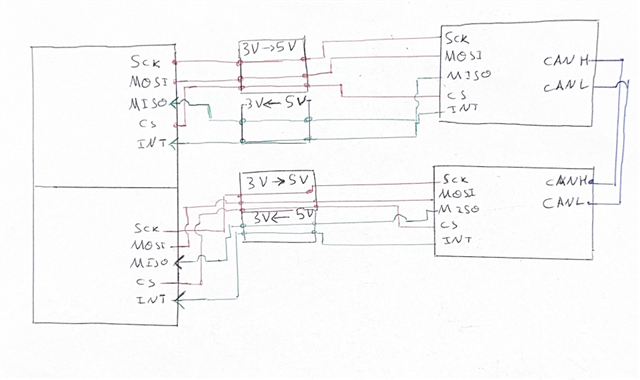
Each DK is wired to the usual “all-in-one” MCP2515 + TJA1050 8 MHz breakout board, through a 3 V 5 V level-shifter.
Both DKs share CAN H/L and 120 Ω termination, so the setup is basically:
nRF5340 DK #1  <--SPI3-->  MCP2515 board  <--TJA1050-->  CAN bus
nRF5340 DK #2  <--SPI3-->  MCP2515 board  <--TJA1050-->  CAN bus
I’m on Zephyr 4.1.99 (built from current main), using the in-tree MCP2515 driver.
Symptoms
-
can_start(can_dev)returns -5 (-EIO) every time. -
When I manually read the registers right after a software reset I get
CANCTRL = 0xFF
CANSTAT = 0xFF          (sometimes 0x00 after I keep CS low)
which looks like no response from the MCP2515 at all.
-
With an oscilloscope I can see SCK ≈ 1 MHz and MOSI activity,
but CS stays low (driver-controlled) and MISO never toggles.
What I already tried
-
Verified 5 V on MCP2515 VDD and 8 MHz crystal is running.
-
Forced a software reset sequence (
0xC0), small delay, then raw SPI read ofCANSTAT→ still0xFF/0x00. -
Added explicit bit-timing for the 8 MHz crystal (250 kbit/s) before
can_start()– no change. -
Toggling CS manually in the application proves the pin & level-shifter work; as soon as the driver owns CS it sits low.
-
Moving the module to a spare STM32 board shows it is alive, so the hardware itself is OK.
Minimal files
prj.conf
CONFIG_GPIO=y
CONFIG_PINCTRL=y
CONFIG_SPI=y
CONFIG_SPI_ASYNC=y
CONFIG_CAN=y
CONFIG_CAN_MCP2515=y

CONFIG_PRINTK=y
CONFIG_MAIN_STACK_SIZE=2048
Overlay (nrf5340dk_nrf5340_cpuapp.overlay)
/* SPI3 on DK  (P0.04 SCK, P0.05 MOSI, P0.06 MISO, P0.25 CS) */
&pinctrl {
    spi3_default: spi3_default {
        group1 {
            psels = <
                NRF_PSEL(SPIM_SCK,  0, 4)
                NRF_PSEL(SPIM_MOSI, 0, 5)
                NRF_PSEL(SPIM_MISO, 0, 6)
            >;
        };
    };
    spi3_sleep: spi3_sleep {
        group1 {
            psels = <
                NRF_PSEL(SPIM_SCK,  0, 4)
                NRF_PSEL(SPIM_MOSI, 0, 5)
                NRF_PSEL(SPIM_MISO, 0, 6)
            >;
            low-power-enable;
        };
    };
};

&spi3 {
    status = "okay";
    pinctrl-0 = <&spi3_default>;
    pinctrl-1 = <&spi3_sleep>;
    pinctrl-names = "default", "sleep";
    cs-gpios = <&gpio0 25 GPIO_ACTIVE_LOW>;

    mcp2515: can0@0 {
        compatible        = "microchip,mcp2515";
        reg               = <0>;
        spi-max-frequency = <1000000>;
        osc-freq          = <8000000>;
        bus-speed         = <250000>;     /* 250 kbit/s */
        int-gpios         = <&gpio1 15 GPIO_ACTIVE_LOW>;
        status            = "okay";
        label             = "CAN_0";
    };
};

/* disable unused SPIM to silence pinctrl warnings */
&spi0 { status = "disabled"; };
&spi1 { status = "disabled"; };
&spi2 { status = "disabled"; };
&spi4 { status = "disabled"; };
Excerpt of the test main.c
static const struct device *const can_dev = DEVICE_DT_GET(DT_NODELABEL(mcp2515));
static const struct spi_dt_spec mcp_spi =
        SPI_DT_SPEC_GET(DT_NODELABEL(mcp2515),
                        SPI_WORD_SET(8) | SPI_OP_MODE_MASTER | SPI_TRANSFER_MSB,
                        0);

void main(void)
{
    /* give the 8 MHz crystal some time */
    k_sleep(K_MSEC(5));

    /* --- software reset --- */
    uint8_t rst = 0xC0;
    struct spi_buf b = { &rst, 1 };
    struct spi_buf_set s = { &b, 1 };
    spi_write_dt(&mcp_spi, &s);
    k_sleep(K_MSEC(2));

    /* quick CANSTAT read */
    uint8_t cmd[3] = { 0x03, 0x0E, 0x00 };   /* READ 0x0E */
    uint8_t rx[3]  = { 0 };
    struct spi_buf tx = { cmd, sizeof(cmd) };
    struct spi_buf rxbuf = { rx, sizeof(rx) };
    struct spi_buf_set TX = { &tx, 1 }, RX = { &rxbuf, 1 };
    spi_transceive_dt(&mcp_spi, &TX, &RX);
    printk("CANCTRL 0x%02X  CANSTAT 0x%02X\n", rx[1], rx[2]);  /* both 0xFF */

    struct can_timing t = {
        .prescaler  = 1,
        .sjw        = 1,
        .prop_seg   = 5,
        .phase_seg1 = 5,
        .phase_seg2 = 5,
    };
    can_set_timing(can_dev, &t);

    int ret = can_start(can_dev);   /* always ret = -5 */
    printk("can_start() -> %d\n", ret);
}
Question
What else should I check?
-
Is there something obvious in my overlay / pinctrl that would keep CS low?
-
Do I have to patch the MCP2515 driver for an 8 MHz oscillator (BRP tables)?
-
Any clue why the device just returns
0xFFon every read (→ tri-stated MISO)?
I’d be grateful for any hint
Thanks!