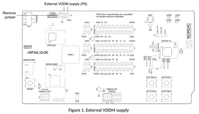
the older nrf52-DK has a header for external and one for current measurement.... how do i achieve something similar on the nrf54L15-DK, which exposes the 3-pin P6 header????
Hi Bob,
To achieve external supply you need to connect to the two rightmost pins. If you want to achieve both at the same time you can measure the nRF54L15 SoC current while supplying it from an external source by connecting your measurement instrument in series with the VDDM line at P6.
Also check out Direct Supply and Current Measurements in the docs.
I hope this answered your question.
Best regards,
Benjamin
seems to work.... if i directly supply power, am i bypassing the PMIC??? if i actually source 1.8V (as opposed to 3.3V) my overall energy consumption is better.... from what i can tell, this is equivalent to USB power which (by default) goes to 1.8V via the PMIC.... the VDDM test point on the board seems to reflect this, correct???
If you supply the voltage through the header then the VDD of the DK should be set to the same as the external voltage to ensure the current measurements are correct and to avoid damaging the DK OBD.
Yes, that is correct. Using an external supply bypasses the PMIC. On the nRF54L15 DK, only the SoC itself is powered from this external source. To avoid connecting its pins to unpowered devices, make sure the 5 V domain is supplied through the interface debugger USB connector (J3).