Hello everyone,
I'm curretly working on a new design based on nrf52832, and I'm validating different interfaces.
Currently working on SPI, I'm testing it with a W25Q64 Flash and the PCA10040DK (nrf52832DK) and the spi_flash sample on NRF Connect SDK v3.0.2.
This nrf52dk_nbrf52832.overlay files works :
&spi1 {
status = "okay";
cs-gpios = <&gpio0 15 GPIO_ACTIVE_LOW>;
pinctrl-0 = <&spi1_default>;
pinctrl-1 = <&spi1_sleep>;
pinctrl-names = "default", "sleep";
w25q64: flash@0 {
compatible = "jedec,spi-nor";
label = "W25Q64";
reg = <0>;
spi-max-frequency = <8000000>; /* nRF52 limit */
jedec-id = [ef 40 17];
size = <0x800000>; /* 8 MiB */
};
};
&pinctrl {
spi1_default: spi1_default {
group1 {
psels = <NRF_PSEL(SPIM_SCK, 0, 31)>,
<NRF_PSEL(SPIM_MOSI, 0, 30)>,
<NRF_PSEL(SPIM_MISO, 0, 29)>;
};
};
spi1_sleep: spi1_sleep {
group1 {
psels = <NRF_PSEL(SPIM_SCK, 0, 31)>,
<NRF_PSEL(SPIM_MOSI, 0, 30)>,
<NRF_PSEL(SPIM_MISO, 0, 29)>;
low-power-enable;
};
};
};
It works and logs :
W25Q64 SPI flash testing
========================
Perform test on single sector
Test 1: Flash erase
Flash erase succeeded!
Test 2: Flash write
Attempting to write 4 bytes
Data read matches data written. Good!!
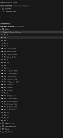
But on my design I'd like to use
P0.16 as SCK
P0.13 as MOSI
========================
Perform test on single sector
Test 1: Flash erase
Flash erase succeeded!
Test 2: Flash write
Attempting to write 4 bytes
Data read matches data written. Good!!
But on my design I'd like to use
P0.16 as SCK
P0.13 as MOSI
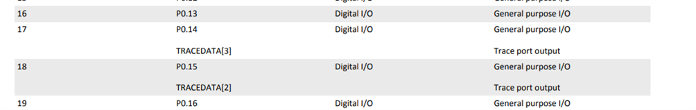
P0.14 as as MISO
And when I switch to it :
 I don't see anythiong on the datasheet that would explain this, except maybe the TRACEDATA but I'm using RTT and logged NRF_CLOCK->TRACECONFIG == 0 so I guess this should'nt be a problem ?
Anyway this is where I'm at so far, maybe some of you will help me with your lights I hope :)
Have a good weekend,
Regards,
Aloïs KYROU
And when I switch to it :
spi1_default: spi1_default {
group1 {
psels = <NRF_PSEL(SPIM_SCK, 0, 16)>,
<NRF_PSEL(SPIM_MOSI, 0, 13)>,
<NRF_PSEL(SPIM_MISO, 0, 14)>;
};
};
spi1_sleep: spi1_sleep {
group1 {
psels = <NRF_PSEL(SPIM_SCK, 0, 16)>,
<NRF_PSEL(SPIM_MOSI, 0, 13)>,
<NRF_PSEL(SPIM_MISO, 0, 14)>;
low-power-enable;
};
};
The sample logs :
W25Q64: device not ready.
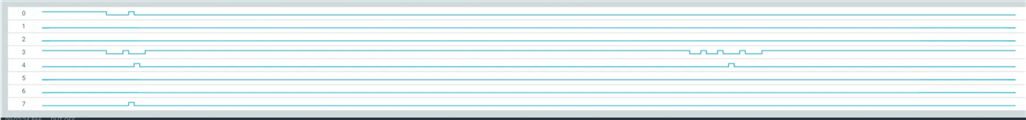
I've tried to look up what's happen on the analyser :
When it fails :
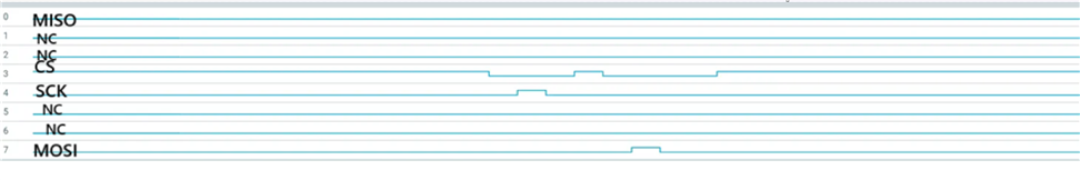
When it succeeds :
The sample logs :
W25Q64: device not ready.
I've tried to look up what's happen on the analyser :
When it fails :
When it succeeds :
Anyway this is where I'm at so far, maybe some of you will help me with your lights I hope :)
Have a good weekend,
Regards,
Aloïs KYROU