Weak TX output power - HW design problem?

Hi,

I made a custom board with nRF54L15. I do not have a spectrum analyzer, so I cannot tune how much power goes to the antenna or how much is radiated. So, I started ADV on my board and used a mobile app to check the received RSSI. When I compared it with the nRF52-DK kit, which has a PCB antenna, I got a much weaker signal from my board than from the DK kit - when I am at the same distance, about 1 meter from the transmitter, my signal is about 20 dBm lower.

Is there something really wrong with my board? I also tried a version without the switch - only one antenna  and the result was almost the same. I know it is not easy to tune this way, but I am happy for any ideas or advice.

Thank you.

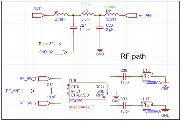
Schematic:  I could not buy inductors with 3.5 nH on Farnell, so I used 3.3 nH instead.


Layout:
Impedance of path should be 50 ohm:


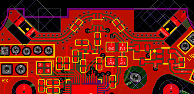
The ground is under RF path, but only in this part (under L9) is path for + 3.3 Volts:


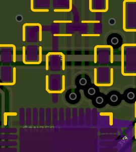
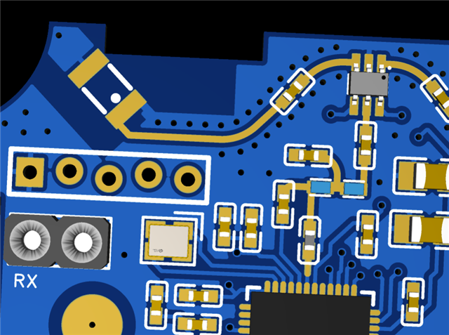
Space on the PCB is not large, so I choose this kind of antenna, but if you have any other reccomendations for better ant, please tell me.

Parents
  • hello,

    A 20 dBm lower RSSI almost certainly points to a hardware/layout issue, not just the small inductor value change. The screenshot you uploaded here, can not see any antenna matching network there. Can you send us the hardware design file including schematic and pcb layout files?

  • Hi, Thank you.

    I thought that if the output after the passives from the nRF54L is 50 ohms, and the antenna input is also 50 ohms, then it is enough to just connect these two parts (and put an RF switch between them). But if I do not have a vector analyzer, I probably will not be able to choose the correct values for antenna matching, right?

    Should I send the data - in PDF? Gerber files? The project in EasyEDA Pro?

    In the meantime, I tried to remove the antenna and instead put a piece of wire (25 mm) as a monopole, and the signal level improved a lot. So I guess the problem is in my design somewhere at the very end, at the antenna.

Reply
  • Hi, Thank you.

    I thought that if the output after the passives from the nRF54L is 50 ohms, and the antenna input is also 50 ohms, then it is enough to just connect these two parts (and put an RF switch between them). But if I do not have a vector analyzer, I probably will not be able to choose the correct values for antenna matching, right?

    Should I send the data - in PDF? Gerber files? The project in EasyEDA Pro?

    In the meantime, I tried to remove the antenna and instead put a piece of wire (25 mm) as a monopole, and the signal level improved a lot. So I guess the problem is in my design somewhere at the very end, at the antenna.

Children
No Data
Related