Hi,
I made a custom board with nRF54L15. I do not have a spectrum analyzer, so I cannot tune how much power goes to the antenna or how much is radiated. So, I started ADV on my board and used a mobile app to check the received RSSI. When I compared it with the nRF52-DK kit, which has a PCB antenna, I got a much weaker signal from my board than from the DK kit - when I am at the same distance, about 1 meter from the transmitter, my signal is about 20 dBm lower.
Is there something really wrong with my board? I also tried a version without the switch - only one antenna and the result was almost the same. I know it is not easy to tune this way, but I am happy for any ideas or advice.
Thank you.
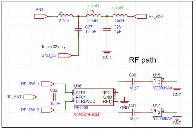
Schematic: I could not buy inductors with 3.5 nH on Farnell, so I used 3.3 nH instead.

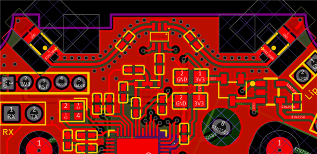
Layout:
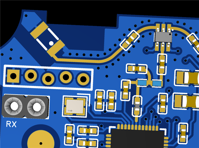
Impedance of path should be 50 ohm:
The ground is under RF path, but only in this part (under L9) is path for + 3.3 Volts:

Space on the PCB is not large, so I choose this kind of antenna, but if you have any other reccomendations for better ant, please tell me.

