Incorrect current measurements with PPK2 when using an nPM2100

Hello,

I am experiencing issues with the current measurements taken by the PPK2 when using the nPM2100-EK to power a device. The current drawn from the 2.7V power source (PPK2) is lower when using the nPM2100 (configured to output 3.0V) compared to a direct connection without the nPM. This is clearly incorrect. How should the PPK2 be configured to reliably measure our system, including the nPM2100?

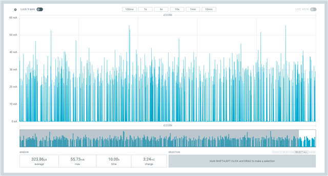
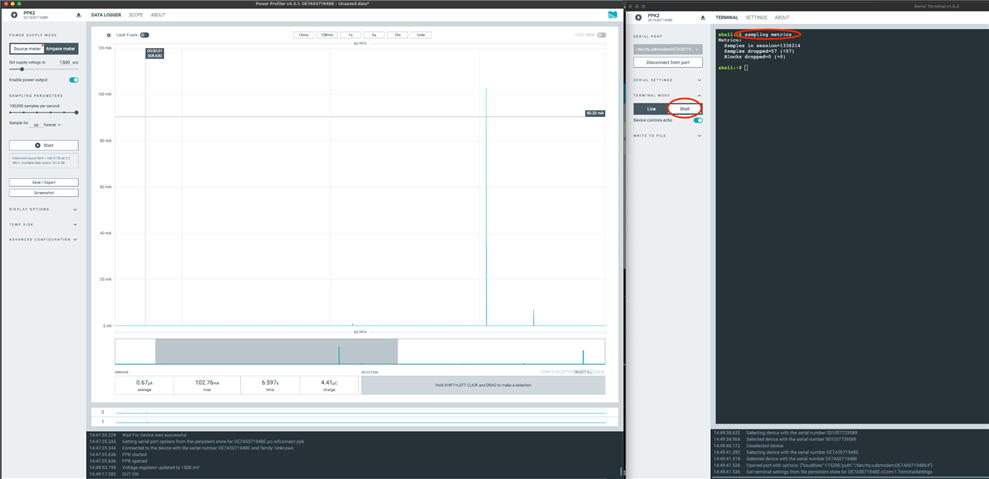
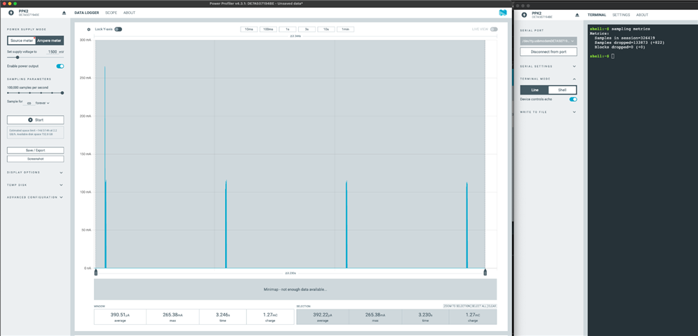
The system is a Bluetooth-enabled measurement device that uses an nRF52840 chip. When connected to a Bluetooth master, the system draws an average current of around 530µA at 2.7V, which is quite high for a CRxxxx coin cell primary battery. Therefore, I would like to use the nPM2100 to boost the voltage to a constant value of 3.0V. However, when using the nPM2100-EK for this purpose, the PPK2's current measurement shows large spikes and an average value of only 320µA. As the nPM2100 does not generate energy, this measurement must be incorrect. 

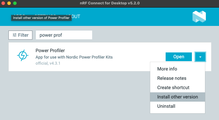
I am using Power Profiler Version 4.2.2 and even a second PPK2 produces similarly incorrect results. I have read about the phantom spikes occurring at the highest sampling rate. I therefore selected a sampling rate of 10kHz, but the values are still incorrect.

Has anyone else experienced this issue? What is wrong with the PPK2 measurements?

  • Hello Runar,

    Sorry for the late response. I was on holiday for the last two weeks.

    Yes, I have read the notes on taking measurements using the PPK. I used the PPK in source meter mode to supply power to the nPM2100-EK. 

    However, I did not use the nRF Connect Powerup application to configure the evaluation kit. Instead, I only used the jumpers available on the board, configured as follows:

    P1     all open    BATTERY INPUT
    P2     2.7V         VBAT
    P3     all open    RESERVOIR CAP
    P5     all open    LDO OUT
    P6     all open    
    P7     1.5V         VEXT LEVEL
    P8     3.0V         VSET
    P9     7.5kΩ res.VOUT
    P10   OFF         BOOT MON
    P11   all open    TWI
    P12   all open    GPIO
    P13   all open    CONFIG
    P14   all open    LOAD SEL
    SW5  VBAT       VBAT SEL

    My EK board version is PCA10170 / 0.8.0 / 2024.50

    I hope this information will help you reproduce my issue.

    Best regards

    David

  • Hello David,
    I've tried replicating your setup here now and I measure larger inrush currents to the capacitors on the nPM2100 DK on P3 if I have one or several of those connected. You write that your P3 is all open, have you removed the jumpers from P3 all together? Do you see a difference if you actually switch back and connect one of the reservoir caps?
    I do also see some refresh spikes when I'm disconnecting the reservoir caps, but average current is as expected.
    Have you tried switching to using the amp meter function on the output from the nPM2100 to see if the reading you get in that mode make more sense for your setup?
    Best regards
    Asbjørn
  • Hello Asbjørn,

    Thank you for your response. You are right; I removed all the jumpers from P3 on the nPM2100-EK. Therefore, there are only two capacitors remain on the Vint line (C6 and C7; C8 is not soldered to the board). When I reconnect some more capacitance using jumpers on P3, the input current spikes increase to up to 50mA, but the average current measured by the PPK2 at 2.7V is still below the output current of the nPM2100 at 3.0V, so the result is still incorrect. However, a digital ammeter connected between the PPK2 and the nPM2100 measures an average current of around 530µA, which seems OK. 

    When I use the PPK2 in ammeter mode at the output of the nPM2100-EK, the current measurements are still incorrect. It measures around 30µA flowing through my 7.5kΩ resistor. 

    As I have two PPK2s, I tried something else that makes me doubt the accuracy of the PPK2. I configured the first PPK2 in source mode to output 3V and connected the second one in series with a 7.5kΩ resistor in ammeter mode. Both PPK2s measure the same current, but the first one shows around 390µA and the second one only 80µA. When I switch their roles, they measure 350µA and 30µA respectively.

    Can you explain that ? Are both of my PPK2s broken ?

    Best regards

    David

  • Hello David, 
    had some discussion here with others and in general the PPK2 might struggle with certain loads, especially if there is a lot of transients which I think you are seeing.
    Three things; 
    First is capacitance on the input to the nPM2100 might not be sufficient. Are you able to add large capacitors on the output from the PPK2 or input on the nPM2100-EK? 2x10uF could be a start to see if it stabilises the measurements. 
    Secondly, the FW on the PPK2 can discard measurements. When the PPK2 firmware suspects there is a measurement error caused by a measurement range transition happening at an inopportune time, the measurement is discarded.
    You can retrieve metrics from the PPK2 as described below. If there is a high amount of “samples dropped”, this would indicate that the PPK2 struggles with this particular load.
    The more recent version of PPK2  firmware has a 2nd tty/COM port that can be used for shell access. Open this port using for example the nRF Connect Serial Terminal application, and execute the “$ sampling metrics” shell command after you have stopped sampling.
    (The shell is by design unresponsive while sampling is active)
    This screenshot is taken without any load on nPM2100 EK VOUT.  VBAT = 1.5 V, VOUT = 3 V
    Adding a 20 mA load pulse lasting 10 ms at 1 Hz generates more dropped samples:
    Thirdly, it’s also possible to compare with an older PPK2 firmware version by downgrading the Power Profiler app to v4.1.3:
    So if you add capacitance and check if there number of dropped measurements decline or goes to zero, you should get more reasonable numbers.
    Best regards
    Asbjørn
  • Dear Asbjørn,

    Thank you for discussing the topic internally and for sharing your new insights. You are right. As the nPM2100 produces significant current spikes, the PPK2 is probably not the most suitable equipment for measuring its input current.

    According to the shell's output, the percentage of dropped samples is generally below 0.5%. Only the measurements taken with 10µF of capacitance on VINT (no jumper on P3, minimum value) produced higher values (between 3% and 4%) and the resulting average current was clearly incorrect. 

    Downgrading the PowerProfiler software to v4.1.3 also downgrades the PPK2 firmware to an earlier version, predating the introduction of shell access. Therefore, I was unable to check the dropped samples. However, this version does not improve the measurement accuracy.

    Adding 2x10µF of capacitance to VSUPPLY, together with minimum capacitance on VINT, results in a more accurate average current reading (500µA in my test case). Increasing the capacitance on VINT degrades the measurement values. 

    Currently, the only way to obtain correct values from the PPK2 is to perform a measurement with an ammeter connected in series with the nPM2100-EK. However, the µA scale on my ammeter incorporates a 100Ω resistor, creating a voltage drop in the EK's input voltage.

    Having said that, I'm slightly confused because the nPM2100-EK User Guide suggests using the PPK2 to measure the nPM2100's currents. Have you tried this method? I am certainly not the only one having trouble getting an accurate measurement with the PPK2. What is your opinion on this? Are you developing new software / firmware for the PPK2 that would be more effective in this situation?

    Best regards

    David

Related