Hello,
I am working on a new hardware design of analog sensors, which I want to sample their reading using SAADC.
I use nrf52832 PCA10040 DK, and softdevice s132 for sending data over BLE.
The thing is that I have been trying for a while to read properly the sensors which are connected to each other in a grid form as i will describe below. In order to evaluate my code first, I created the same grid with resistors, so I know the expected values.
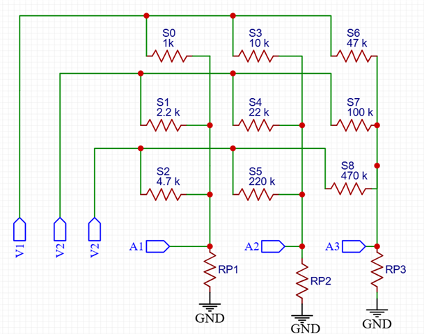
the grid is: 
Which is 9 resistors, with 3 signal lines and 3 power lines.
S0, S1, S2 are connected to the same analog pin A1,
S3, S4, S5 are connected to the same analog pin A2,
S6, S7, S8 are connected to the same analog pin A3. (every column of the grid is connected to the same analog input pin)
while
S0, S3, S6 are connected to the same power line, and respectively every row of the grid is connected to the same power line.
The idea is that if we disconnect every pin and set only V1 high and connect only A1 analog pin to the ADC, we will read the "signal" of the resistor S0 only without any interference of the rest.
However, I have not got yet the expected results and I would like some help if there is something wrong in the pin handling or generally in the code or maybe there is something wrong with the circuit that I have not thought and the reading of a specific resistor without cross-talk is impossible.
Here is the timeout handler in main that handles the changes of the selected sensor and saadc initializations
uint8_t column = 0;
uint8_t sensor = 0;
uint16_t total_sensors[9] = {0};
uint8_t count = 0;

void adjustment_functionality(void)
{
    ret_code_t err_code;
    uint16_t live_measurements_adj[3];


     if(!nrf_saadc_enable_check())
     {
         if(column == 0)
         {
            saadc_init_channel_0();
         }
         else if(column == 1)
         {
            saadc_init_channel_1();
         }
         else if(column == 2)
         {
            saadc_init_channel_2();
         }
         connect_row(sensor);
         nrf_delay_ms(10);
     }
     buffer_convert();

   //led_toggle(BLUE_LED);


   if(get_flag() == true)
   {
        get_live_measurements(live_measurements_adj);


        total_sensors[sensor] = live_measurements_adj[0];


       //if(err_code == NRF_SUCCESS)
       //if(sensor == 0)
       //{
        NRF_LOG_INFO("Adjustment Sent (column %d, sensor %d)  %d %d %d  ", column, sensor,total_sensors[0],total_sensors[3],total_sensors[6]);
        NRF_LOG_INFO("                                        %d %d %d  ",total_sensors[1],total_sensors[4],total_sensors[7]);
        NRF_LOG_INFO("                                        %d %d %d  ",total_sensors[2],total_sensors[5],total_sensors[8]);
        //}

       count++;

       if(count==20)
       {
           sensor++;

           if(sensor == 3 || sensor == 6)
            {
                column++;
                saadc_abort();
                nrf_delay_ms(10);
            }
           if(sensor == 9)
            {
              column = 0;
              sensor = 0;
              saadc_abort();
              nrf_delay_ms(10);

            }
            count = 0;
       }


        set_flag_false();
   }

   err_code = app_timer_start(m_measurements_timer_id, SAADC_INTERVAL, NULL);

}
the saadc initializations (I tried to use different channel for each analog pin)
void saadc_init_channel_0(void)
{
  ret_code_t err_code;
  nrf_drv_saadc_config_t saadc_config = NRF_DRV_SAADC_DEFAULT_CONFIG;
  nrf_saadc_channel_config_t channel0_config;
  m_saadc_calibrate = true;

  //Configure SAADC

  saadc_config.low_power_mode = true;                           //Enable low power mode.
  saadc_config.resolution = NRF_SAADC_RESOLUTION_14BIT;         //Set SAADC resolution to 14-bit. This will make the SAADC output values from 0 (when input voltage is 0V) to 2^14=4096 (when input voltage is VDD for channel gain setting of 1/4).
  saadc_config.oversample = NRF_SAADC_OVERSAMPLE_DISABLED;      //Set oversample to 4x. This will make the SAADC output a single averaged value when the SAMPLE task is triggered 4 times.
  saadc_config.interrupt_priority = APP_IRQ_PRIORITY_LOW;       //Set SAADC interrupt to low priority.

  //Initialize SAADC
  err_code = nrf_drv_saadc_init(&saadc_config, saadc_callback); //Initialize the SAADC with configuration and callback function. The application must then implement the saadc_callback function, which will be called when SAADC interrupt is triggered
  UNUSED_VARIABLE(err_code);

  //Configure SAADC channels
  channel0_config.reference  = NRF_SAADC_REFERENCE_VDD4;    //Set internal reference VDD/4.
  channel0_config.gain       = NRF_SAADC_GAIN1_4;           //Set input gain to 1/4. The maximum SAADC input voltage is then VDD/(1/4)= VDD. The single ended input range is then 0V-VDD.
  channel0_config.acq_time   = NRF_SAADC_ACQTIME_40US;      //Set acquisition time. Set low acquisition time to enable maximum sampling frequency of 200kHz. Set high acquisition time to allow maximum source resistance up to 800 kohm, see the SAADC electrical specification in the PS.
  channel0_config.mode       = NRF_SAADC_MODE_SINGLE_ENDED; //Set SAADC as single ended. This means it will only have the positive pin as input, and the negative pin is shorted to ground (0V) internally.
  channel0_config.burst      = NRF_SAADC_BURST_DISABLED;    //Configure burst mode for channel 0. Burst is useful together with oversampling. When triggering the SAMPLE task in burst mode, the SAADC will sample "Oversample" number of times as fast as it can and then output a single averaged value to the RAM buffer. If burst mode is not enabled, the SAMPLE task needs to be triggered "Oversample" number of times to output a single averaged value to the RAM buffer.
  channel0_config.pin_p      = NRF_SAADC_INPUT_AIN2;        //Select the input pin for the channel.
  channel0_config.pin_n      = NRF_SAADC_INPUT_DISABLED;    //Since the SAADC is single ended, the negative pin is disabled. The negative pin is shorted to ground internally.
  channel0_config.resistor_p = NRF_SAADC_RESISTOR_PULLDOWN; //Disable the 13k pulldown resistor. (Bypass resistor ladder).
  channel0_config.resistor_n = NRF_SAADC_RESISTOR_DISABLED; //Disable pulldown resistor on the input pin

  //Initialize SAADC channels
  err_code = nrf_drv_saadc_channel_init(0, &channel0_config);    //Initialize channel 0 with its configuration
  UNUSED_VARIABLE(err_code);

  //nrf_drv_saadc_channel_uninit(1);
  //nrf_drv_saadc_channel_uninit(2);

  //connect_pulldown_resistors();
  nrf_gpio_cfg_input(4, NRF_GPIO_PIN_PULLDOWN);

  NRF_LOG_INFO(" SAADC INIT CHANNEL 0 -------");
}

void saadc_init_channel_1(void)
{
  ret_code_t err_code;
  nrf_drv_saadc_config_t saadc_config = NRF_DRV_SAADC_DEFAULT_CONFIG;
  nrf_saadc_channel_config_t channel1_config;

  m_saadc_calibrate = true;

  //Configure SAADC

  saadc_config.low_power_mode = true;                           //Enable low power mode.
  saadc_config.resolution = NRF_SAADC_RESOLUTION_14BIT;         //Set SAADC resolution to 14-bit. This will make the SAADC output values from 0 (when input voltage is 0V) to 2^14=4096 (when input voltage is VDD for channel gain setting of 1/4).
  saadc_config.oversample = NRF_SAADC_OVERSAMPLE_DISABLED;      //Set oversample to 4x. This will make the SAADC output a single averaged value when the SAMPLE task is triggered 4 times.
  saadc_config.interrupt_priority = APP_IRQ_PRIORITY_LOW;       //Set SAADC interrupt to low priority.

  //Initialize SAADC
  err_code = nrf_drv_saadc_init(&saadc_config, saadc_callback); //Initialize the SAADC with configuration and callback function. The application must then implement the saadc_callback function, which will be called when SAADC interrupt is triggered
  UNUSED_VARIABLE(err_code);

  //Configure SAADC channels


  channel1_config.reference  = NRF_SAADC_REFERENCE_VDD4;    //Set internal reference VDD/4.
  channel1_config.gain       = NRF_SAADC_GAIN1_4;           //Set input gain to 1/4. The maximum SAADC input voltage is then VDD/(1/4)= VDD. The single ended input range is then 0V-VDD.
  channel1_config.acq_time   = NRF_SAADC_ACQTIME_40US;      //Set acquisition time. Set low acquisition time to enable maximum sampling frequency of 200kHz. Set high acquisition time to allow maximum source resistance up to 800 kohm, see the SAADC electrical specification in the PS.
  channel1_config.mode       = NRF_SAADC_MODE_SINGLE_ENDED; //Set SAADC as single ended. This means it will only have the positive pin as input, and the negative pin is shorted to ground (0V) internally.
  channel1_config.burst      = NRF_SAADC_BURST_DISABLED;    //Configure burst mode for channel 0. Burst is useful together with oversampling. When triggering the SAMPLE task in burst mode, the SAADC will sample "Oversample" number of times as fast as it can and then output a single averaged value to the RAM buffer. If burst mode is not enabled, the SAMPLE task needs to be triggered "Oversample" number of times to output a single averaged value to the RAM buffer.
  channel1_config.pin_p      = NRF_SAADC_INPUT_AIN3;        //Select the input pin for the channel.
  channel1_config.pin_n      = NRF_SAADC_INPUT_DISABLED;    //Since the SAADC is single ended, the negative pin is disabled. The negative pin is shorted to ground internally.
  channel1_config.resistor_p = NRF_SAADC_RESISTOR_PULLDOWN; //Disable the 13k pulldown resistor. (Bypass resistor ladder).
  channel1_config.resistor_n = NRF_SAADC_RESISTOR_DISABLED; //Disable pulldown resistor on the input pin


  //Initialize SAADC channels


   err_code = nrf_drv_saadc_channel_init(1, &channel1_config);    //Initialize channel 0 with its configuration
  UNUSED_VARIABLE(err_code);


  //nrf_drv_saadc_channel_uninit(0);
  //nrf_drv_saadc_channel_uninit(2);

  //connect_pulldown_resistors();
  nrf_gpio_cfg_input(5, NRF_GPIO_PIN_PULLDOWN);

  NRF_LOG_INFO(" SAADC INIT CHANNEL 1 -------");
}

void saadc_init_channel_2(void)
{
  ret_code_t err_code;
  nrf_drv_saadc_config_t saadc_config = NRF_DRV_SAADC_DEFAULT_CONFIG;
  nrf_saadc_channel_config_t channel2_config;
  m_saadc_calibrate = true;

  //Configure SAADC

  saadc_config.low_power_mode = true;                           //Enable low power mode.
  saadc_config.resolution = NRF_SAADC_RESOLUTION_14BIT;         //Set SAADC resolution to 14-bit. This will make the SAADC output values from 0 (when input voltage is 0V) to 2^14=4096 (when input voltage is VDD for channel gain setting of 1/4).
  saadc_config.oversample = NRF_SAADC_OVERSAMPLE_DISABLED;      //Set oversample to 4x. This will make the SAADC output a single averaged value when the SAMPLE task is triggered 4 times.
  saadc_config.interrupt_priority = APP_IRQ_PRIORITY_LOW;       //Set SAADC interrupt to low priority.

  //Initialize SAADC
  err_code = nrf_drv_saadc_init(&saadc_config, saadc_callback); //Initialize the SAADC with configuration and callback function. The application must then implement the saadc_callback function, which will be called when SAADC interrupt is triggered
  UNUSED_VARIABLE(err_code);

  //Configure SAADC channel
  channel2_config.reference  = NRF_SAADC_REFERENCE_VDD4;    //Set internal reference VDD/4.
  channel2_config.gain       = NRF_SAADC_GAIN1_4;           //Set input gain to 1/4. The maximum SAADC input voltage is then VDD/(1/4)= VDD. The single ended input range is then 0V-VDD.
  channel2_config.acq_time   = NRF_SAADC_ACQTIME_40US;      //Set acquisition time. Set low acquisition time to enable maximum sampling frequency of 200kHz. Set high acquisition time to allow maximum source resistance up to 800 kohm, see the SAADC electrical specification in the PS.
  channel2_config.mode       = NRF_SAADC_MODE_SINGLE_ENDED; //Set SAADC as single ended. This means it will only have the positive pin as input, and the negative pin is shorted to ground (0V) internally.
  channel2_config.burst      = NRF_SAADC_BURST_DISABLED;    //Configure burst mode for channel 0. Burst is useful together with oversampling. When triggering the SAMPLE task in burst mode, the SAADC will sample "Oversample" number of times as fast as it can and then output a single averaged value to the RAM buffer. If burst mode is not enabled, the SAMPLE task needs to be triggered "Oversample" number of times to output a single averaged value to the RAM buffer.
  channel2_config.pin_p      = NRF_SAADC_INPUT_AIN4;        //Select the input pin for the channel.
  channel2_config.pin_n      = NRF_SAADC_INPUT_DISABLED;    //Since the SAADC is single ended, the negative pin is disabled. The negative pin is shorted to ground internally.
  channel2_config.resistor_p = NRF_SAADC_RESISTOR_PULLDOWN; //Disable the 13k pulldown resistor. (Bypass resistor ladder).
  channel2_config.resistor_n = NRF_SAADC_RESISTOR_DISABLED; //Disable pulldown resistor on the input pin

  //Initialize SAADC channels


   err_code = nrf_drv_saadc_channel_init(2, &channel2_config);    //Initialize channel 0 with its configuration
  UNUSED_VARIABLE(err_code);

  //nrf_drv_saadc_channel_uninit(1);
  //nrf_drv_saadc_channel_uninit(0);

  //connect_pulldown_resistors();
  nrf_gpio_cfg_input(28, NRF_GPIO_PIN_PULLDOWN);

  NRF_LOG_INFO(" SAADC INIT CHANNEL 2 -------");
}
the function that turns on and off the power lines for each row of sensors.
void connect_row(uint8_t sensor)
{
  if(sensor==0 || sensor==3 || sensor==6)
  {
      NRF_LOG_INFO("CONNECT ROW 1 (0, 3, 6) for sensor %d", sensor);
      //nrf_gpio_pin_clear(V2);
      //nrf_delay_ms(10);
      //nrf_gpio_pin_clear(V3);
      //nrf_delay_ms(10);
      nrf_gpio_cfg_input(V2, NRF_GPIO_PIN_NOPULL);
      nrf_gpio_input_disconnect(V2);
      nrf_gpio_cfg_input(V3, NRF_GPIO_PIN_NOPULL);
      nrf_gpio_input_disconnect(V3);
      nrf_gpio_cfg_output(V1);
      nrf_gpio_pin_set(V1);
      nrf_delay_ms(10);
  }
  else if(sensor==1 || sensor==4 || sensor==7)
  {
      NRF_LOG_INFO("CONNECT ROW 2 (1, 4, 7) for sensor %d", sensor);
      //nrf_gpio_pin_clear(V1);
      //nrf_delay_ms(10);
      //nrf_gpio_pin_clear(V3);
      //nrf_delay_ms(10);
      nrf_gpio_cfg_input(V1, NRF_GPIO_PIN_NOPULL);
      nrf_gpio_input_disconnect(V1);
      nrf_gpio_cfg_input(V3, NRF_GPIO_PIN_NOPULL);
      nrf_gpio_input_disconnect(V3);
      nrf_gpio_cfg_output(V2);
      nrf_gpio_pin_set(V2);
      nrf_delay_ms(10);
  }
  else //row 3
  {
      NRF_LOG_INFO("CONNECT ROW 3 (2, 5, 8) for sensor %d", sensor);
      //nrf_gpio_pin_clear(V1);
      //nrf_delay_ms(10);
      //nrf_gpio_pin_clear(V2);
      //nrf_delay_ms(10);
      nrf_gpio_cfg_input(V1, NRF_GPIO_PIN_NOPULL);
      nrf_gpio_input_disconnect(V1);
      nrf_gpio_cfg_input(V2, NRF_GPIO_PIN_NOPULL);
      nrf_gpio_input_disconnect(V2);
      nrf_gpio_cfg_output(V3);
      nrf_gpio_pin_set(V3);
      nrf_delay_ms(10);
  }

}
So, what I did so far is :
1. Initialize saadc channel 0 (which is for S0,S1,S2)
1.1. Turn on V1, take 20 samples of S0
1.2 Disconnect V1 and turn on V2, take samples of S1,
1.3 Disconnect V1, turn on V3, take samples of S2,
2. Initialize saadc channel 1 (which is for S3,S4,S5)
2.1. Disconnect V3, turn on V1, take samples of S3 etc...
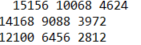
Expected values (since there is an internal resistor 13k and using the formula of pull-down resistor):
[S0, S3, S6] [15232, 9259, 3550]
[S1, S4, S7] = [14015, 6086, 1884]
[S2, S5, S8] [12034, 914, 441]
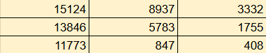
And what i get is this :

So the first column is quite close, but the rest isn't. Is it something impossible due to hardware design what i am trying to achieve or am I doing something wrong?
I will also try with a multiplexer while i am waiting for an answer here..
Thank you in advance