
I am having issues getting the BMI270 sample working on an NRF54l15-DK, using nRF Connect SDK v3.0.2 and toolchain 3.0.2. After successfully building and flashing the program to nRF54L15DK, I got the error "Device BMI270 is not ready." How can I solve this problem?
I have installed I2C_SHELL and am able to see and access the device using the i2c Shell prompt. unable to access or configure this using devicetree. device list is showing as disabled. explored the option of status= "okay"; not solving the problem.
Need help.
I am using the following config and overlay files.
prj.config
# General config
CONFIG_ASSERT=y
CONFIG_NEWLIB_LIBC=y
CONFIG_STDOUT_CONSOLE=y
CONFIG_PRINTK=y
CONFIG_CBPRINTF_FP_SUPPORT=y

CONFIG_SPI=y
CONFIG_SHELL=y
CONFIG_SENSOR=y
CONFIG_SENSOR_SHELL=y
CONFIG_SENSOR_LOG_LEVEL_DBG=y
# CONFIG_SENSOR_ASYNC_API=y

CONFIG_PWM=y

# enable console
CONFIG_CONSOLE=y
CONFIG_UART_CONSOLE=y

# Enable RTT
#CONFIG_USE_SEGGER_RTT=n
#CONFIG_RTT_CONSOLE=n

#I2C configuration
CONFIG_I2C=y
CONFIG_I2C_SHELL=y
CONFIG_I2C_NRFX=y
CONFIG_I2C_LOG_LEVEL_DBG=y

CONFIG_LLEXT_EXPORT_DEVICES=y

CONFIG_BMI270=y
nrf54l15.overlay
/* The NRF54L DK cannot have both i2c21. uart21 and spi21 enabled concurrently */

&spi21 { status = "disabled"; };
&uart21 { status = "disabled"; };
/* &spi00 { status = "disabled"; }; */

/*This is the i2c21 node that is used to connect the BMI270 and CAP1293 sensors.
   The BMI270 is a 6-axis IMU sensor, and the CAP1293 is a capacitive touch sensor.
   The i2c21 node is configured with the appropriate pinctrl settings for default and sleep modes.
   The sensors are defined as children of the i2c21 node with their respective addresses and properties. */

&i2c21 {
    status = "okay";
    compatible = "nordic,nrf-twim","i2c-device";
    pinctrl-0 = <&i2c21_default>;
    pinctrl-1 = <&i2c21_sleep>;
    pinctrl-names = "default","sleep";
    clock-frequency = <I2C_BITRATE_STANDARD>;

    bmi270:bmi270@69 {
        status = "okay";
        compatible = "bosch,bmi270"; // ,"bosch,bmi270,base";
		reg = <0x69>;
		label = "BMI270_ACEL_GYRO";
        irq-gpios = <&gpio1 15 GPIO_ACTIVE_HIGH>;
        zephyr,deferred-init;
        wakeup-source;
        zephyr,pm-device-runtime-auto;
    };

    cap1293:cap12xx@28 {
        status = "okay";
        compatible = "microchip,cap12xx";
        reg = <0x28>;
        label = "cap1293";
        #address-cells = <1>;
        #size-cells = <0>;
       // interrupt-parent = <&gpio0>;
       // interrupts = <1 IRQ_TYPE_EDGE_RISING>;
        input-codes = <INPUT_KEY_0>, <INPUT_KEY_1>, <INPUT_KEY_2>;
        // int-gpios = <&gpio2 0 0>;
        // repeat;
    };

    max30101:max30101@57 {
        status = "okay";
        compatible = "maxim,max30101";
        reg = <0x57>;
        label = "MAX30101";
    };

    };

&pinctrl {
    /omit-if-no-ref/ i2c21_default: i2c21_default {
        group1 {
            psels = < NRF_PSEL(TWIM_SCL, 1, 11)>, <NRF_PSEL(TWIM_SDA, 1, 12)>;  /* P1.2 → SCL  & P1.3 → SDA*/
            bias-pull-up; /* i2c needs to be pulled up if Pull up resistors are not connected */
                };
        };
    /omit-if-no-ref/ i2c21_sleep: i2c21_sleep {
        group1 {
            psels = <NRF_PSEL(TWIM_SDA, 1, 11)>, <NRF_PSEL(TWIM_SCL, 1, 12)>;
            low-power-enable;
                };
        };
};


/*
&i2c21 {
    bmi270@69 { status = "okay"; };
    cap1239: cap1239@28 {  status = "okay"; };
    };
*/
/{
    aliases {
            bmi270 = &bmi270;
            cap1293 = &cap1293;
            max30101 = &max30101;
        };
};
Main.c program
#include <zephyr/kernel.h>
#include <zephyr/sys/printk.h>
#include <zephyr/device.h>
#include <zephyr/drivers/i2c.h>
#include <zephyr/drivers/pwm.h>
#include <zephyr/drivers/sensor.h>
#include <zephyr/devicetree.h>
#include <stdio.h>
#include <zephyr/logging/log.h>
#define I2C21_NODEx DT_NODELABEL(bmi270)
#define I2C21_NODEy DT_NODELABEL(cap1293)
int main(void)
{
uint32_t max_period;
uint32_t period;
uint8_t dir = 0U;
int ret;
printk("Starting BMI270 sensor example ...\n");
static const struct i2c_dt_spec i2c_dev1 = I2C_DT_SPEC_GET(I2C21_NODEx);
static const struct i2c_dt_spec cap1293_i2c = I2C_DT_SPEC_GET(I2C21_NODEy);
if (!device_is_ready(i2c_dev1.bus)) {
printk("Error: I2C device %s is not ready\n", i2c_dev1.bus->name);
return 0;
}
else {
//LOG_DBG("Device %s is ready", dev_i2c.bus->name);
printk("BMI270 device %s is ready\n", i2c_dev1.bus->name);
}
.....
// i2c working code
/* Program to validate the CHIP ID for BMI270 */
#define BMI270_CHIP_ID_REG 0x00
#define BMI270_CHIP_ID 0x24
uint8_t chip_id = 0;
uint8_t reg = BMI270_CHIP_ID_REG;
int ret1 = i2c_write_read_dt(&dev_i2c, ®, 1, &chip_id, 1);
if (ret1 != 0) {
printk("Failed to read chip ID register\n");
} else if (chip_id != BMI270_CHIP_ID) {
printk("Unexpected chip ID: 0x%02x\n", chip_id);
} else {
printk("BMI270 detected, chip ID: 0x%02x\n", chip_id);
}
.......
output :
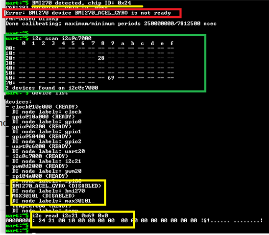
The i2c scanner shows the device, and I am able to access it in the shell prompt and read the device.
Any help is greatly appreciated!

