UART Rx interrupt not enabled after PM_DEVICE_ACTION_RESUME

Hello,

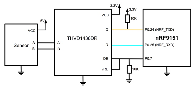
I'm adding power management to a custom driver that talks to a sensor via uart2 of the nRF9151DK. But from my tests it seems that uart_irq_rx_enable()  has no effect after the driver resumes the uart device with pm_device_runtime_get().

The driver has three functions:

turn_on(): Runs pm_device_runtime_get() to resume uart operation and sets a gpio high to enable the sensor.

turn_off(): Runs pm_device_runtime_put() to suspend uart operation and set a gpio low to disable the sensor.

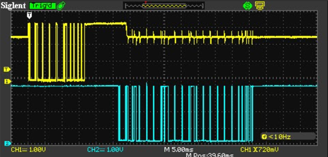
sample_fetch(): Sends a command to the sensor and waits for the rx buffer to have the expected response size in bytes, using a semaphore with a 1s timeout.

The pm_action callback function is:


static int sensor_pm_action(const struct device *dev,
                             enum pm_device_action action)
{
    const struct sensor_cfg *cfg = dev->config;
    struct gpio_dt_spec en_gpio = cfg->en_gpio;
    int ret = 0;

    switch (action)
    {
    case PM_DEVICE_ACTION_RESUME:
        LOG_INF("Resuming sensor");
        
        /* Re-initialize the sensor */
        ret = sensor_init(dev);
        break;

    case PM_DEVICE_ACTION_SUSPEND:
        LOG_INF("Suspending sensor");
        
        /* Disconnect GPIO */
        gpio_pin_configure((&en_gpio)->port, (&en_gpio)->pin, GPIO_INPUT | GPIO_DISCONNECTED);

        break;
    default:
        return -ENOTSUP;
    }

    return ret;
}

 The driver init function sets up the uart paramenters:

static int sensor_init(const struct device *dev)
{
    const struct sensor_cfg *cfg = dev->config;
    struct sensor_data *data = dev->data;
    struct gpio_dt_spec en_gpio = cfg->en_gpio;
    int ret = 0;

    LOG_DBG("Initializing sensor driver");

    if (!gpio_is_ready_dt(&en_gpio))
    {
        LOG_ERR("Sensor EN pin not ready");
        return -ENOSYS;
    }

    gpio_pin_configure((&en_gpio)->port, (&en_gpio)->pin, GPIO_OUTPUT);
    gpio_pin_set_dt(&en_gpio, 0);

    if (!device_is_ready(cfg->uart_dev))
    {
        LOG_ERR("UART not ready");
        return -ENOSYS;
    }

    uart_irq_rx_disable(cfg->uart_dev);
    uart_irq_tx_disable(cfg->uart_dev);

    ret = uart_configure(cfg->uart_dev, &uart_cfg_sensor);

    if (ret == -ENOSYS)
    {
        LOG_ERR("Unable to configure UART port");
        return -ENOSYS;
    }

    ret = uart_irq_callback_user_data_set(cfg->uart_dev, cfg->cb, (void *)dev);

    if (ret < 0)
    {
        if (ret == -ENOTSUP)
        {
            LOG_ERR("Interrupt-driven UART API support not enabled");
        }
        else if (ret == -ENOSYS)
        {
            LOG_ERR("UART device does not support interrupt-driven API");
        }
        else
        {
            LOG_ERR("Error setting UART callback: %d", ret);
        }
        return ret;
    }

    if (ret == -ENOSYS)
    {
        LOG_ERR("Unable to configure UART");
        return -ENOSYS;
    }

    data->rx_index = 0;
    data->tx_index = 0;

    k_sem_init(&data->tx_sem, 1, 1);
    k_sem_init(&data->rx_sem, 0, 1);

    return ret;
}

App overlay file:

&uart2 {
    status = "okay";
    current-speed = <4800>;
    pinctrl-0 = <&uart2_default>;
    pinctrl-1 = <&uart2_sleep>;
    pinctrl-names = "default", "sleep";
    zephyr,pm-device-runtime-auto;

    sensor_test: sensor {
        compatible = "sensor";
        en-gpios = <&gpio0 7 GPIO_ACTIVE_HIGH>;
        status = "okay";
        zephyr,pm-device-runtime-auto;
    };
};

&pinctrl {
    uart2_default: uart2_default {
        group1 {
            psels = <NRF_PSEL(UART_TX, 0, 24)>,
                    <NRF_PSEL(UART_RTS, 0, 23)>;
        };
        group2 {
            psels = <NRF_PSEL(UART_RX, 0, 25)>,
                    <NRF_PSEL(UART_CTS, 0, 17)>;
            bias-pull-up;
        };
    };

    uart2_sleep: uart2_sleep {
        group1 {
            psels = <NRF_PSEL(UART_TX, 0, 24)>,
                    <NRF_PSEL(UART_RX, 0, 25)>,
                    <NRF_PSEL(UART_RTS, 0, 23)>,
                    <NRF_PSEL(UART_CTS, 0, 17)>;
            low-power-enable;
        };
    };
};

And prj.conf file:

CONFIG_GPIO=y
CONFIG_LOG=y
CONFIG_SERIAL=y
CONFIG_CONSOLE=y

CONFIG_UART_INTERRUPT_DRIVEN=y
CONFIG_SENSOR=y
CONFIG_CUSTOM_SENSOR_DRIVER=y
CONFIG_CUSTOM_SENSOR=y

CONFIG_PM_DEVICE=y
CONFIG_PM_DEVICE_RUNTIME=y

CONFIG_TFM_SECURE_UART=n
CONFIG_TFM_LOG_LEVEL_SILENCE=y

If the  zephyr,pm-device-runtime-auto is removed from the uart node in devicetree, the driver gets the response form the sensor.

Any ideas of what is causing this? Thanks!

Best regards,

Lalo

Parents
  • Hi,


    If the  zephyr,pm-device-runtime-auto is removed from the uart node in devicetree, the driver gets the response form the sensor.

    If you remove this, then it works without any issues?

    I would recommend that you check the state, as shown in the docs if my understanding of the issue is correct:

    https://docs.zephyrproject.org/latest/services/pm/device_runtime.html


    Q1: Have you scoped the TXD and RXD lines to confirm the behavior?

    Q2: do you have any debug logs showing the issue?

    It seems that you are always running sensor_init(), meaning that the uart will be re-initialized each time. That will cause a ret != 0 for that function.


    Kind regards,

    Håkon

  • Hi Håkon, 

    If you remove this, then it works without any issues?

    Yes, sorry if I didn't give more details, I followed your sugestion and removed sensor_init() from the sensor_pm_action() callback.

    I'm still getting the same results, with this overlay I get an Rx timeout:

    &uart2 {
        status = "okay";
        current-speed = <4800>;
        pinctrl-0 = <&uart2_default>;
        pinctrl-1 = <&uart2_sleep>;
        pinctrl-names = "default", "sleep";
        zephyr,pm-device-runtime-auto;
    
        sensor_test: sensor {
            compatible = "sensor";
            en-gpios = <&gpio0 7 GPIO_ACTIVE_HIGH>;
            status = "okay";
            zephyr,pm-device-runtime-auto;
        };
    };

    -----------------------------------------------------------------------

    *** Booting nRF Connect SDK v3.0.2-89ba1294ac9b ***
    *** Using Zephyr OS v4.0.99-f791c49f492c ***
    [00:00:00.390,655] <inf> sensor_pm_test: Sensor Test Started
    [00:00:00.390,686] <inf> test_sensor: Resuming sensor
    [00:00:02.391,052] <err> test_sensor: Rx Timeout!
    [00:00:02.391,082] <err> sensor_pm_test: Could not fetch sample (-62)
    [00:00:02.391,113] <inf> test_sensor: Suspending sensor

    -----------------------------------------------------------------------

    If I remove the zephyr,pm-device-runtime-auto:

    &uart2 {
        status = "okay";
        current-speed = <4800>;
        pinctrl-0 = <&uart2_default>;
        pinctrl-1 = <&uart2_sleep>;
        pinctrl-names = "default", "sleep";
        
        sensor_test: sensor {
            compatible = "sensor";
            en-gpios = <&gpio0 7 GPIO_ACTIVE_HIGH>;
            status = "okay";
            zephyr,pm-device-runtime-auto;
        };
    };
     

    I get a valid response from the sensor:
    -----------------------------------------------------------------------
    *** Booting nRF Connect SDK v3.0.2-89ba1294ac9b ***
    *** Using Zephyr OS v4.0.99-f791c49f492c ***
    [00:00:00.414,825] <inf> sensor_pm_test: Sensor Test Started
    [00:00:00.414,855] <inf> test_sensor: Resuming sensor
    [00:00:01.488,067] <dbg> test_sensor: sensor_uart_isr: Sensor Resp>>
                                                                   01 03 0e 00 00 01 00 00 00 00 1e 00 00 00 00 00 |........ ........
                                                                   00 ec d7 00 00 00 00 00 00 00 00 00 00 00 00 00 |........ ........
    [00:00:01.488,128] <inf> test_sensor: Suspending sensor
    -----------------------------------------------------------------------
    For reference, this is the uart ISR handler function:
    static void sensor_uart_isr(const struct device *uart_dev, void *user_data)
    {
        const struct device *dev = user_data;
        struct sensor_data *data = dev->data;
    
        ARG_UNUSED(user_data);
    
        if (uart_dev == NULL)
        {
            return;
        }
    
        if (!uart_irq_update(uart_dev))
        {
            LOG_DBG("Unable to start processing interrupts");
            return;
        }
    
        if (uart_irq_rx_ready(uart_dev))
        {
            data->rx_index += uart_fifo_read(uart_dev, &data->rx_buffer[data->rx_index], RESP_SIZE - data->rx_index);
    
            if (data->rx_index == RESP_SIZE)
            {
                LOG_HEXDUMP_DBG(data->rx_buffer, sizeof(data->rx_buffer), "Sensor Resp>>");
                data->rx_index = 0;
                uart_irq_rx_disable(uart_dev);
                k_sem_give(&data->rx_sem);
            }
        }
    
        if (uart_irq_tx_ready(uart_dev))
        {
            data->tx_index +=
                uart_fifo_fill(uart_dev, &data->tx_buffer[data->tx_index],
                               CMD_SIZE - data->tx_index);
    
            if (data->tx_index == CMD_SIZE)
            {
                data->tx_index = 0;
                uart_irq_tx_disable(uart_dev);
                k_sem_give(&data->tx_sem);
            }
        }
    }
    And the sample_fetch function:

    static int sample_fetch(const struct device *dev)
    {
        struct sensor_data *data = dev->data;
        struct sensor_cfg *cfg = dev->config;
        int ret;
        const uint8_t cmd[] = {0x01, 0x03, 0x00, 0x00, 0x00, 0x07, 0x04, 0x08};
    
        memset(data->tx_buffer, '\0', sizeof(data->tx_buffer));
    
        for (size_t i = 0; i < sizeof(cmd); i++)
        {
            data->tx_buffer[i] = cmd[i];
        }
    
        data->rx_index = 0;
        data->tx_index = 0;
    
        ret = k_sem_take(&data->tx_sem, SERIAL_TIMEOUT);
        if (ret < 0)
        {
            LOG_ERR("Tx Timeout!");
            return -ETIME;
        }
    
        k_sem_reset(&data->rx_sem);
        uart_irq_tx_enable(cfg->uart_dev);
        uart_irq_rx_enable(cfg->uart_dev);
    
        ret = k_sem_take(&data->rx_sem, SERIAL_TIMEOUT);
    
        if (ret < 0)
        {
            LOG_ERR("Rx Timeout!");
            return -ETIME;
        }
    
        .....
        Process data...
        .....
    
        return 0;
    }
    I checked the Tx/Rx lines with an oscilloscope and found a strange behavior in the Rx timeout case (Tx-yellow, Rx-blue):
     
    This is the trace for the valid response:
     
     
  • Is your sensor and the nRF9151 (VDDIO net) running on the same voltage?

    Or is it such that you remove power from your external sensor? If yes, then you need to remove the pull-up inside the RXD pin (and set TXD low), as these will then back-power your sensor.


    Kind regards,

    Håkon

Reply Children
  • Hi Håkon,

    The sensor is powered from the 5V rail on the DK and has an RS-485 interface, so I'm using this transceiver powered from the VIO (3.3V) rail, both remain powered during the test.

    The DK's Rx line has an external pull-up on the transceiver board.

    Best regards,

    Lalo 

  • Hi,


    Lalo_16 said:
    The sensor is powered from the 5V rail on the DK and has an RS-485 interface

    Can you share a schematic or similar on how this is setup? There's an enable pin in the mix here as well on P0.07, what is its function?


    What is the configured IO voltage of the nRF9151-DK? This is set in your board configurator:

    https://docs.nordicsemi.com/bundle/nrf-connect-board-configurator/page/updating.html

    Or you can just measure it with a multimeter.


    It is hard to see what line is from the nRF and which is from the sensor, NRF_RXD or is it SENSOR_RXD that is misbehaving?


    If both are indeed on the same voltage level, it does seem like there's an output vs. an output, and the strongest one drags it up to approx. 2.5V:


    Teal line does not seem to have this issue.


    Kind regards,

    Håkon

  • Can you share a schematic or similar on how this is setup? There's an enable pin in the mix here as well on P0.07, what is its function?

    P0.07 is connected to the transceiver's EN pin.

    What is the configured IO voltage of the nRF9151-DK?

    3.3V

    It is hard to see what line is from the nRF and which is from the sensor, NRF_RXD or is it SENSOR_RXD that is misbehaving?

    The teal trace is NRF_RXD, in both cases -with an wihout zephyr,pm-device-runtime-auto selected in the uart node-, the sensor sends a valid response. So the Rx timeout should be related to the pm config and not hardware related.

    Best regards,

    Lalo  

  • Hi,


    Could you share a schematic or any info about your sensor setup?

    Håkon Alseth said:
    Can you share a schematic or similar on how this is setup?

    NRF_RXD shall be driven by the EXT_SENSOR_TXD pin.

    One of the sides is pulling the pin. If you disconnect either side, you can measure which side tries to pull low.

    If it is the NRF, check the NRF_GPIO register for the specific pin to see if it is set as output low.


    Kind regards,

    Håkon

  • Hi Håkon,

    Could you share a schematic or any info about your sensor setup?

    The colors correspond to the scope traces mentioned above.

    As mentioned before, regardless of whether zephyr,pm-device-runtime-auto is enabled under the uart node, the trace shows a response in the NRF_RXD (teal trace) pin.

    The strange behavior of the NRF_TXD (yellow trace) when zephyr,pm-device-runtime-auto is enabled -although not optimal- is not affecting the correct transmition of the command to the sensor, and the subsequent response from the sensor is received in the NRF_RXD pin. 

    This in my opinion discards any hardware related issues and points to some configuration issue in the uart power management that is not enabling rx interrupts when the device is reactivated.

    BR,

    Lalo

Related