Flashing nrf54L05 chipset

Hi All,

We have an application that was compiled on nrf54L15DK where we get UART logs . The application was tested on DK and is working fine. 

Use Case:

Wanted to run the same application onto nrf54L05 chipset. Followed the below steps.

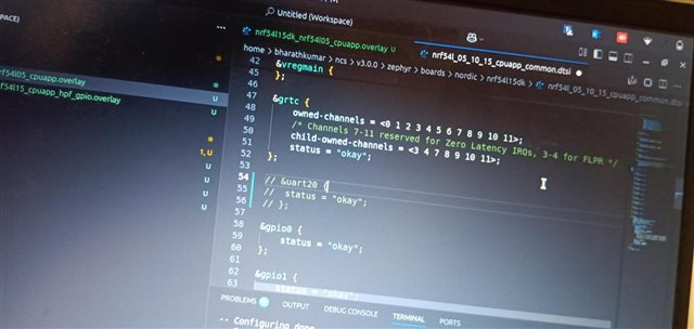
1. Changed the overlay file name to nrf54L15dk_nrf54l05_cpuapp.overlay 

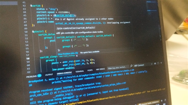
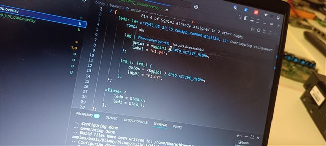
2. Modified the UART pins in .overlay file as per new custom boards requirement.

Then flashed the merged.hex file using nrf connect desktop programmer Tool via nrf52840DK. The program seemed to be flashed. Below is the screenshot of the same.

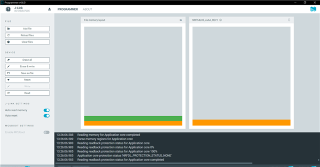
But We dont get the intended logs on the UART lines. Are we missing something ? 

Is there any other way to flash the custom board ?

Parents
  • Hi,

    I assumed you in addition to making a file called nrf54L15dk_nrf54l05_cpuapp.overlay also have a build target that is nrf54l15dk/nrf54l05/cpuapp.

    Do your custom board have an external 32kHz crystal?

    Kenneth


  • Hi  ,

    I have created the overlay file as well as build target is nrf54l15dk/nrf54l05/cpuapp while generating the hex file. 

    We have an external 32kHz crystal as well on the custom board. I have used P2.2 and P2.0 as the UART tx and rx lines respectively. I am not getting logs which I am intended to . The same code works in nrf54l15dk by changing the overlay file and build target. 

    In my custom board's overlay file, I can see overlapping assignment . The screenshot is attached here. 

    I can share the working overlay file of nrf54L15DK and the non working file of nrf54L05 custom board here as well.

    / {
        nrf_radio_fem: name_of_fem_node {
            compatible  = "nordic,nrf21540-fem";
            tx-en-gpios = <&gpio1 10 GPIO_ACTIVE_HIGH>;
            rx-en-gpios = <&gpio1 11 GPIO_ACTIVE_HIGH>;
            pdn-gpios   = <&gpio1 12 GPIO_ACTIVE_HIGH>;
        };
    };
    
    &dppic10 {
        status = "okay";
    };
    
    &ppib11 {
        status = "okay";
    };
    
    &ppib21 {
        status = "okay";
    };
    
    &dppic20 {
        status = "okay";
    };
    
    &ppib22 {
        status = "okay";
    };
    
    &ppib30 {
        status = "okay";
    };
    
    &dppic30 {
        status = "okay";
    };


    &uart20 {
        status = "okay";
        current-speed = <115200>;
        pinctrl-0 = <&uart20_default>;
        pinctrl-1 = <&uart20_sleep>;
        pinctrl-names = "default", "sleep";
    };
    
    &pinctrl {
        uart20_default: uart20_default {
            group1 {
                psels = <NRF_PSEL(UART_TX, 2, 2)>,  // TX on P2.02
                        <NRF_PSEL(UART_RX, 2, 0)>;  // RX on P2.00
            };
        };
    
        uart20_sleep: uart20_sleep {
            group1 {
                psels = <NRF_PSEL(UART_TX, 2, 2)>,
                        <NRF_PSEL(UART_RX, 2, 0)>;
                low-power-enable;
            };
        };
    };
    
    /{
    chosen {
        zephyr,console = &uart20;
        zephyr,shell-uart = &uart20;
    	};
    };
    
    
    / {
        nrf_radio_fem: name_of_fem_node {
            compatible  = "nordic,nrf21540-fem";
            tx-en-gpios = <&gpio1 7 GPIO_ACTIVE_HIGH>;
            rx-en-gpios = <&gpio1 8 GPIO_ACTIVE_HIGH>;
            pdn-gpios   = <&gpio1 9 GPIO_ACTIVE_HIGH>;
        };
    };
    
    &dppic10 {
        status = "okay";
    };
    
    &ppib11 {
        status = "okay";
    };
    
    &ppib21 {
        status = "okay";
    };
    
    &dppic20 {
        status = "okay";
    };
    
    &ppib22 {
        status = "okay";
    };
    
    &ppib30 {
        status = "okay";
    };
    
    &dppic30 {
        status = "okay";
    };


    &uart20 {
        status = "okay";
        current-speed = <115200>;
        pinctrl-0 = <&uart20_default>;
        pinctrl-1 = <&uart20_sleep>;
        pinctrl-names = "default", "sleep";
    };
    
    &pinctrl {
        uart20_default: uart20_default {
            group1 {
                psels = <NRF_PSEL(UART_TX, 1, 4)>,  // TX on P1.04
                        <NRF_PSEL(UART_RX, 1, 5)>;  // RX on P1.05
            };
        };
    
        uart20_sleep: uart20_sleep {
            group1 {
                psels = <NRF_PSEL(UART_TX, 1, 4)>,
                        <NRF_PSEL(UART_RX, 1, 5)>;
                low-power-enable;
            };
        };
    };
    
    /{
    chosen {
        zephyr,console = &uart20;
        zephyr,shell-uart = &uart20;
    	};
    };


  • Before you try UART, maybe you can try something simple as checking that all the pins works by for instance toggle them or read the pins if they are intended as inputs?

    Kenneth

Reply Children
  • I have tried blinky example and was successful in blinking LED of P1.04 and P1.07.
    The error which I was encountering while compiling this example is ""Overlapping assignment" of pins in the file 


    So then I clicked on the file which is creating conflicts, it turned out to be the uart20 config in the dts file. 
    I commented that dts config. Then finally blinky started working 


    So, In my actual project which involves the usage of UART, similar error error we are getting. 

    How do we resolve the conflict of overlapping assignment ? 

    I get the following error when we use P2.02 and P2.00 as tx and rx of UART lines. 

Related