Hello Team,
We are using custom nRF52833 with nRF21540 (PCB). we manually controlling the nRF21540 FEM using GPIO and SPI (not using the FEM driver) for testing purpose. After configuring the gain to 20 dBm, I expected significantly increased BLE advertising range. However, I can only scan my device up to 40 meters—beyond that, it's no longer detected.
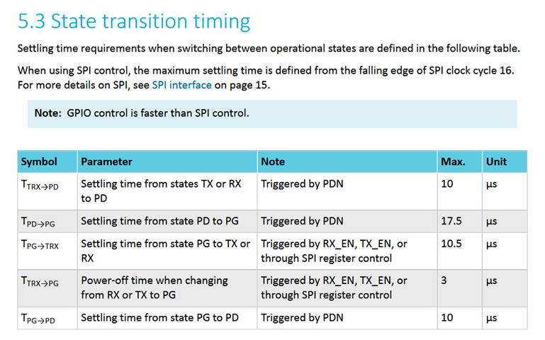
We suspect this could be a timing or configuration issue that prevents the range extender from stabilizing correctly before TX.
Here is my main.c
my main.c

#include <zephyr/kernel.h>
#include <zephyr/drivers/gpio.h>
#include <zephyr/drivers/spi.h>
#include <zephyr/logging/log.h>
#include <zephyr/bluetooth/bluetooth.h>
#include <zephyr/bluetooth/hci.h>
#include <zephyr/bluetooth/uuid.h>

#define DEVICE_NAME " RANGE_2 "
#define DEVICE_NAME_LEN (sizeof(DEVICE_NAME) - 1)


static const struct bt_data ad[] = {
    BT_DATA_BYTES(BT_DATA_FLAGS, (BT_LE_AD_GENERAL | BT_LE_AD_NO_BREDR)),
    BT_DATA(BT_DATA_NAME_COMPLETE, DEVICE_NAME, DEVICE_NAME_LEN),
};

static const struct bt_data sd[] = {
    BT_DATA_BYTES(BT_DATA_UUID128_ALL,
        BT_UUID_128_ENCODE(0x6E400001, 0xB5A3, 0xF393, 0xE0A9, 0xE50E24DCCA9E),
    ),
};

#define ZEPHYR_USER_NODE DT_PATH(zephyr_user)

static const struct gpio_dt_spec xtal_1 = GPIO_DT_SPEC_GET(ZEPHYR_USER_NODE, xtal_1_gpios);
static const struct gpio_dt_spec xtal_2 = GPIO_DT_SPEC_GET(ZEPHYR_USER_NODE, xtal_2_gpios);

LOG_MODULE_REGISTER(main, LOG_LEVEL_INF);


#define SPI_NODE DT_NODELABEL(spi3)
#define CS_GPIO_PORT DT_NODELABEL(gpio0)
#define CS_PIN 4  // Change to your actual CS pin number

static const struct device *spi_dev = DEVICE_DT_GET(SPI_NODE);
static const struct device *cs_gpio_dev = DEVICE_DT_GET(CS_GPIO_PORT);

#define TX_EN_NODE   DT_NODELABEL(nrf21540_tx_en)
#define RX_EN_NODE   DT_NODELABEL(nrf21540_rx_en)
#define PDN_NODE     DT_NODELABEL(nrf21540_pdn)
#define ANT_SEL_NODE DT_NODELABEL(nrf21540_ant_sel)
#define MODE_NODE    DT_NODELABEL(nrf21540_mode)

static const struct gpio_dt_spec tx_en_gpio   = GPIO_DT_SPEC_GET(TX_EN_NODE, gpios);
static const struct gpio_dt_spec rx_en_gpio   = GPIO_DT_SPEC_GET(RX_EN_NODE, gpios);
static const struct gpio_dt_spec pdn_gpio     = GPIO_DT_SPEC_GET(PDN_NODE, gpios);
static const struct gpio_dt_spec ant_sel_gpio = GPIO_DT_SPEC_GET(ANT_SEL_NODE, gpios);
static const struct gpio_dt_spec mode_gpio    = GPIO_DT_SPEC_GET(MODE_NODE, gpios);


static struct spi_config spi_cfg = {
    .operation = SPI_WORD_SET(8) | SPI_OP_MODE_MASTER | SPI_TRANSFER_MSB,
    .frequency = 4000000,
    .slave = 0,
    .cs = NULL, // Manual CS control
};


static uint8_t nrf21540_read_reg(uint8_t reg_addr)
{
    uint8_t tx_buffer[2] = {0x80 | (reg_addr << 1), 0x00};
  //  uint8_t tx_buffer[2] = {0x80 /*| (reg_addr << 1)*/, 0x00};  // 0x80: READ command, reg_addr shifted
    uint8_t rx_buffer[2] = {0};

    struct spi_buf tx_buf = {
        .buf = tx_buffer,
        .len = sizeof(tx_buffer),
    };
    struct spi_buf rx_buf = {
        .buf = rx_buffer,
        .len = sizeof(rx_buffer),
    };
    struct spi_buf_set tx_bufs = {
        .buffers = &tx_buf,
        .count = 1,
    };
    struct spi_buf_set rx_bufs = {
        .buffers = &rx_buf,
        .count = 1,
    };

    gpio_pin_set(cs_gpio_dev, CS_PIN, 0); // CS low
    int err = spi_transceive(spi_dev, &spi_cfg, &tx_bufs, &rx_bufs);
    gpio_pin_set(cs_gpio_dev, CS_PIN, 1); // CS high

    if (err) {
        LOG_INF("SPI read error: %d", err);
        return 0xFF;
    }
    LOG_INF("Read reg 0x%02X: 0x%02X", reg_addr, rx_buffer[1]);
    return rx_buffer[1];
}

static void nrf21540_write_reg(uint8_t reg_addr, uint8_t value)
{
    uint8_t tx_buffer[2] = {0xC0 | (reg_addr << 1), value};
    struct spi_buf tx_buf = {.buf = tx_buffer, .len = sizeof(tx_buffer)};
    struct spi_buf_set tx_bufs = {.buffers = &tx_buf, .count = 1};

    gpio_pin_set(cs_gpio_dev, CS_PIN, 0); // CS low
    int err = spi_write(spi_dev, &spi_cfg, &tx_bufs);
    gpio_pin_set(cs_gpio_dev, CS_PIN, 1); // CS high

    if (err) {
        LOG_INF("SPI write error: %d", err);
    } else {
        LOG_INF("Wrote 0x%02X to reg 0x%02X", value, reg_addr);
    }
}

int main(void)
{
    LOG_INF("nRF21540 Manual GPIO/SPI Example");

    // Configure all FEM control pins as outputs
    gpio_pin_configure_dt(&pdn_gpio, GPIO_OUTPUT_LOW);
    gpio_pin_configure_dt(&tx_en_gpio, GPIO_OUTPUT_LOW);
    gpio_pin_configure_dt(&rx_en_gpio, GPIO_OUTPUT_LOW);
    gpio_pin_configure_dt(&ant_sel_gpio, GPIO_OUTPUT_LOW);
    gpio_pin_configure_dt(&mode_gpio, GPIO_OUTPUT_LOW);
    gpio_pin_configure_dt(&xtal_1, GPIO_DISCONNECTED);
    gpio_pin_configure_dt(&xtal_2, GPIO_DISCONNECTED);

    // Power up FEM
    gpio_pin_set_dt(&pdn_gpio, 1);
    k_msleep(10);

    // Set gain and other controls before enabling TX
    gpio_pin_set_dt(&rx_en_gpio, 0);
    gpio_pin_set_dt(&ant_sel_gpio, 0);
    gpio_pin_set_dt(&mode_gpio, 0);

    // Configure CS pin
    gpio_pin_configure(cs_gpio_dev, CS_PIN, GPIO_OUTPUT_HIGH);

    // Set gain for 20 dBm
    nrf21540_write_reg(0x00, 0x9B);
    k_msleep(100);
    uint8_t reg_value = nrf21540_read_reg(0x00);
    LOG_INF("Current CONFREG0 value: 0x%02X", reg_value);

    k_msleep(2000);

    nrf21540_write_reg(0x00, 0xC7);
    k_msleep(100);
    reg_value = nrf21540_read_reg(0x00);
    LOG_INF("Current CONFREG0 value: 0x%02X", reg_value);

    // Enable TX after gain is set
    gpio_pin_set_dt(&tx_en_gpio, 1);

    k_msleep(10);

    // Bluetooth advertising
    int err = bt_enable(NULL);
    if (err) {
        LOG_INF("Bluetooth init failed (err %d)", err);
        return 0;
    }
    LOG_INF("Bluetooth initialized");

    err = bt_le_adv_start(
        BT_LE_ADV_PARAM(BT_LE_ADV_OPT_CONNECTABLE, 8000, 8000, NULL),
        ad, ARRAY_SIZE(ad), sd, ARRAY_SIZE(sd)
    );
    if (err) {
        LOG_INF("Advertising failed to start (err %d)", err);
        return 0;
    }
    LOG_INF("Advertising successfully started");

    while (1) {
        k_msleep(1000);
    }
    return 0;
}
my prj..conf as:
# Bluetooth configuration
CONFIG_BT=y
CONFIG_BT_PERIPHERAL=y
CONFIG_BT_EXT_ADV=y
CONFIG_BT_BROADCASTER=y
CONFIG_BT_ADV_PROV=y
CONFIG_BT_CTLR_ADV_EXT=y
CONFIG_BT_DEVICE_APPEARANCE=0
CONFIG_BT_LL_SOFTDEVICE=y

# Logging
CONFIG_LOG=y
CONFIG_LOG_DEFAULT_LEVEL=3

CONFIG_CLOCK_CONTROL_NRF_K32SRC_RC=y

CONFIG_GPIO=y
CONFIG_SPI=y

CONFIG_BT_CTLR_TX_PWR_ANTENNA=20

# Config logger
CONFIG_LOG=y
CONFIG_USE_SEGGER_RTT=y
CONFIG_LOG_BACKEND_RTT=y
CONFIG_LOG_BACKEND_UART=n
CONFIG_LOG_PRINTK=n
And RTT logs:
[00:00:00.000,366] <inf> main: nRF21540 Manual GPIO/SPI Example
[00:00:02.110,931] <inf> main: Wrote 0x9B to reg 0x00
[00:00:02.211,090] <inf> main: Read reg 0x00: 0x9B
[00:00:02.211,120] <inf> main: Current CONFREG0 value: 0x9B
[00:00:02.221,252] <inf> bt_sdc_hci_driver: SoftDevice Controller build revision:
2d 79 a1 c8 6a 40 b7 3c f6 74 f9 0b 22 d3 c4 80 |-y..j@.< .t.."...
74 72 82 ba |tr..
[00:00:02.223,968] <inf> bt_hci_core: HW Platform: Nordic Semiconductor (0x0002)
[00:00:02.223,999] <inf> bt_hci_core: HW Variant: nRF52x (0x0002)
[00:00:02.224,029] <inf> bt_hci_core: Firmware: Standard Bluetooth controller
Despite writing the correct gain values and enabling TX_EN, BLE scan range is only about 40m in an open outdoor environment.
-
Is my power-on and register-write sequence sufficient for the nRF21540 to operate at full gain?
-
Is there a known stabilization delay between enabling
PDNorTX_ENand starting BLE advertising? -
Do I need to toggle
RX_ENin a specific way for TX mode? -
Would using the FEM driver provide better timing control than manual GPIO/SPI?