What are the pins defined in Zephyr-RTOS nrf7002eb overlay file (for shield)

I am wanting to use the castellated pinouts on the nRF7002 expansion board.

I have the nrf7002eb.overlay file open and it has defined two pins that do not make sense to me, namely iovdd-ctrl-gpios and srrf-switch-gpios.

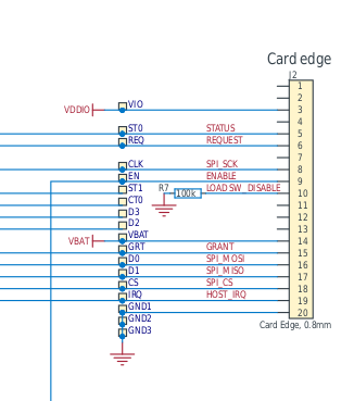
I have downloaded the nRF7002 expansion board's hardware files (nrf7002-expansion-board---hardware-files-0_9_0.zip) to view the schematic.

Neither of those pins can be found in the overlay file are shown.

Also worth noting that when I remove those pins from the overlay file, the compile fails as it is treating iovdd-ctrl-gpios as required. This does not make sense and does not match the yaml file documentation (I tried adding in iovdd-regulator)docs.zephyrproject.org/.../nordic,nrf7002-spi.html

Please could you clarify.

Thanks.

Parents
  • Ah, I was not very observant. I had not noticed that iovdd-ctrl-gpios has the same pin definition as bucken-gpios. They are one and the same. That now makes sense.

    As for srrf-switch-gpios = <&gpio1 13 GPIO_ACTIVE_HIGH>;

    Looking at the nRF53thingy dtsi/dts files it appears at that gpio1 13 is also button 2. So not sure what this gpio is meant to be doing as it is not an edge connection.

Reply
  • Ah, I was not very observant. I had not noticed that iovdd-ctrl-gpios has the same pin definition as bucken-gpios. They are one and the same. That now makes sense.

    As for srrf-switch-gpios = <&gpio1 13 GPIO_ACTIVE_HIGH>;

    Looking at the nRF53thingy dtsi/dts files it appears at that gpio1 13 is also button 2. So not sure what this gpio is meant to be doing as it is not an edge connection.

Children
  • No matter the wiring, I cannot get the nrf7002eb to work.

    Here is my serial output:

    [00:00:00.050,000] <inf> phy_mii: PHY (0) ID 7C131
    --- 6 messages dropped ---
    [00:00:00.055,000] <err> wifi_nrf: nrf_wifi_sys_hal_dev_add: nrf_wifi_bal_dev_add failed
    [00:00:00.055,000] <err> wifi_nrf: nrf_wifi_sys_fmac_dev_add: nrf_wifi_sys_hal_dev_add failed
    [00:00:00.055,000] <err> wifi_nrf: nrf_wifi_fmac_dev_add_zep: nrf_wifi_fmac_dev_add failed
    [00:00:00.055,000] <err> wifi_nrf: nrf_wifi_if_start_zep: nrf_wifi_fmac_dev_add_zep failed
    *** Booting Zephyr OS build v4.2.0-717-g85e135362445 ***
    Set up LED at gpio@58020400 pin 0
    [00:00:00.055,000] <inf> Initializing Wi-Fi driver
    [00:00:00.055,000] <inf> wifi_supplicant: wpa_supplicant initialized
    [00:00:00.056,000] <err> wifi_nrf: nrf_wifi_wpa_supp_set_key: rpu_ctx_zep is NULL
    [00:00:00.056,000] <err> wpa_supp: _wpa_drv_zep_set_key: set_key op failed
    [00:00:00.056,000] <err> wifi_nrf: nrf_wifi_wpa_supp_set_key: rpu_ctx_zep is NULL
    [00:00:00.056,000] <err> wpa_supp: _wpa_drv_zep_set_key: set_key op failed
    [00:00:00.056,000] <err> wifi_nrf: nrf_wifi_wpa_supp_set_key: rpu_ctx_zep is NULL
    [00:00:00.056,000] <err> wpa_supp: _wpa_drv_zep_set_key: set_key op failed
    [00:00:00.056,000] <err> wifi_nrf: nrf_wifi_wpa_supp_set_key: rpu_ctx_zep is NULL
    [00:00:00.056,000] <err> wpa_supp: _wpa_drv_zep_set_key: set_key op failed
    [00:00:00.056,000] <err> wifi_nrf: nrf_wifi_wpa_supp_set_key: rpu_ctx_zep is NULL
    [00:00:00.056,000] <err> wpa_supp: _wpa_drv_zep_set_key: set_key op failed
    [00:00:00.056,000] <err> wifi_nrf: nrf_wifi_wpa_supp_set_key: rpu_ctx_zep is NULL
    [00:00:00.056,000] <err> wpa_supp: _wpa_drv_zep_set_key: set_key op failed

  • Hi,

    You are right about the iovdd-ctrl-gpios. bucken and iovdd-ctrl are control signals from the host into the nRF7002's power path.

    the IOVDD control is commonly tied to the same control line used for bucken-gpios. That’s why you’ll see the same GPIO listed for both bucken-gpios and iovdd-ctrl-gpios.

    On the DK, the host GPIOs that drive the buck/IOVDD switch/RF switch live on the host side. That’s why you’ll see them defined in the overlay, and not as pads labeled exactly that way on the DK. 

    Gerrikoio said:
    As for srrf-switch-gpios

    This is likean optional GPIO which controls an RF switch for short-range coexistence (routes SR RF either to a dedicated SR antenna or a shared antenna with Wi-Fi). It’s only used if the coexistence RF-switch path is enabled in your build. So it's not a DK pad, but more a Thingy:53 's (host's) GPIO. 

    Gerrikoio said:
    Looking at the nRF53thingy dtsi/dts files it appears at that gpio1 13 is also button 2. So not sure what this gpio is meant to be doing as it is not an edge connection.

    Since your Thingy:53 DTS maps P1.13 to a button, then this just means that you got a GPIO conflict in the overlay. So the shield is trying to use the same line for the RF switch. You might need to move it or turn the feature off.

    Could you maybe try to disable the SR coexistence RF switch ? i.e. maybe remove the coex shield/overlay and set
    CONFIG_NRF70_SR_COEX=n and CONFIG_NRF70_SR_COEX_RF_SWITCH=n.

    -Priyanka

Related