Hello there,
we're using multiple pwm-channels of one module of the nRF54L15 for different purposes (multiple motors, h-bridge control; depending on the project).
When the first channel is being turned on or the last channel is being turned off we're seeing spikes on all configured channels - which seems to be unexpected behaviour to us.
We are currently able to work around this (in the h-bridge case just by the correct disable-sequence, in the other case by using different pwm-modules), but still it would be great to have a clean solution here.
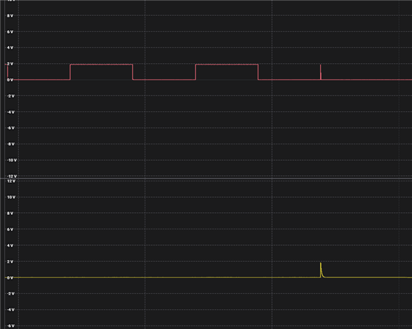
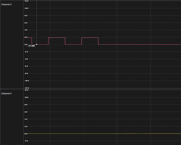
Btw - the off spike looks like it changes the drive-mode of the pin, since it's not a clean edge to GND but looks like a discharge curve.
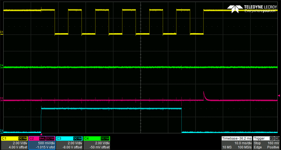
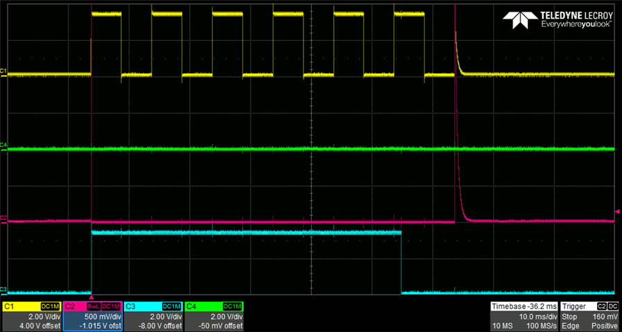
Here is a screenshot of this (I can measure the exact spike width, if needed):
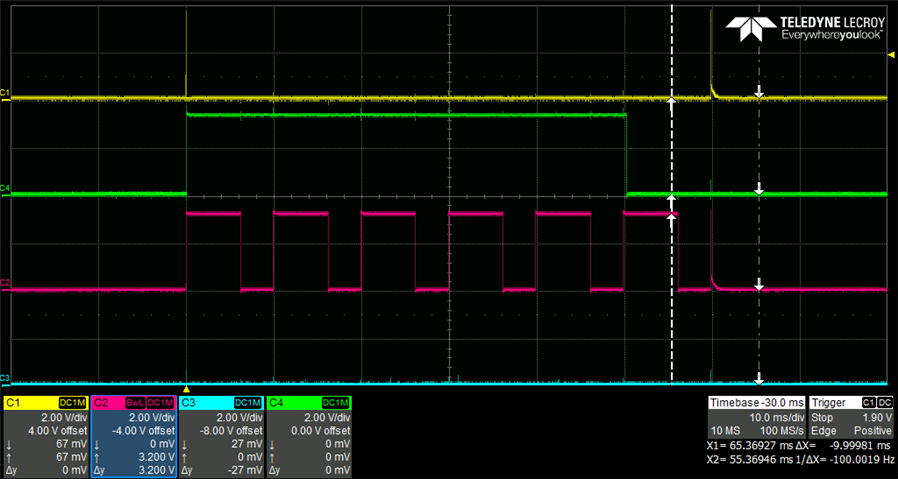
C1 is the inactive pwm-channel, c2 the active one. C3 and C4 are the statically driven gpio's of the h-bridge.
We're on sdk-nrf 3.0.2 and have the following setup:
dts:
/ {
    motor_hbridge_static{
    	compatible = "gpio-leds";
    	motor_common_lowside: motor_common_lowside {
    		gpios = <&gpio1 3 GPIO_ACTIVE_HIGH>;
    		label = "motor common lowside";
    	};
    	motor1_minus_lowside: motor1_minus_lowside {
    		gpios = <&gpio1 2 GPIO_ACTIVE_HIGH>;
    		label = "motor1 minus lowside";
    	};
    };

    motor_hbridge_pwm{
    	compatible = "pwm-leds";
    	motor_common_highside: motor_common_highside{
    		pwms = <&pwm20 0 PWM_USEC(40) PWM_POLARITY_NORMAL>;
    	};
    	motor1_minus_highside: motor1_minus_highside{
    		pwms = <&pwm20 1 PWM_USEC(40) PWM_POLARITY_NORMAL>;
    	};
    };
};

&pinctrl {
	pwm20_default: pwm20_default {
		group1 {
			psels = <NRF_PSEL(PWM_OUT0, 1, 0)>,
					<NRF_PSEL(PWM_OUT1, 1, 1)>;
			nordic,drive-mode = <NRF_DRIVE_H0H1>;
		};
	};
	pwm20_sleep: pwm20_sleep {
		group1 {
			psels = <NRF_PSEL(PWM_OUT0, 1, 0)>,
					<NRF_PSEL(PWM_OUT1, 1, 1)>;
			low-power-enable;
			nordic,drive-mode = <NRF_DRIVE_H0H1>;
		};
	};
};

&pwm20 {
	status = "okay";
	pinctrl-0 = <&pwm20_default>;
	pinctrl-1 = <&pwm20_sleep>;
	pinctrl-names = "default", "sleep";
	zephyr,pm-device-runtime-auto;
};
Test-code:
void test_fn(void)
{
    motor_start(MOTOR_DRIVE_LEFT, MOTOR_PWM_FREQUENCY_LOW, 5000, 8000);
    k_sleep(K_MSEC(50));
    motor_stop();
    k_sleep(K_SECONDS(2));
}

int motor_start(enum motor_drive drive, enum motor_pwm_frequency freq, uint16_t target_voltage_mv, uint16_t voltage_mv)
{
    motor_stop();
    m_motor.drive                                       = drive;
    motor_set_target_voltage(target_voltage_mv);
    motor_set_pwm_frequency(freq);
    motor_update(voltage_mv, 0);
    return 0;
}

int motor_update(uint16_t voltage_mv, uint16_t current_ma)
{
    uint32_t period = PWM_MSEC(10); // 100 Hz
    if (m_motor.frequency == MOTOR_PWM_FREQUENCY_HIGH) {
        period = PWM_USEC(40); // 25 kHz
    }

    uint32_t pulse = (uint32_t)((uint64_t)((uint64_t)period * (uint64_t)m_motor.target_voltage_mv) / voltage_mv); //) / m_motor.target_voltage_mv;

    enum motor_drive drv = m_motor.drive;
    if (drv != MOTOR_DRIVE_RIGHT && drv != MOTOR_DRIVE_LEFT) {
        LOG_ERR("Wrong drive mode. Not driving...");
        return -ENOTSUP;
    }

    pwm_set_dt(m_bridge_pairs[drv].inactive_pwm, period, 0);
    k_sleep(K_USEC(10));
    pwm_set_dt(m_bridge_pairs[drv].active_pwm, period, pulse);
    k_sleep(K_USEC(10));
    gpio_pin_set_dt(m_bridge_pairs[drv].active_gpio, 1);
    gpio_pin_set_dt(m_bridge_pairs[drv].inactive_gpio, 0);

    LOG_DBG("%s: pulse/period: %d / %d", __FUNCTION__, pulse, period);
    return 0;
}

void motor_stop(void)
{

    gpio_pin_set_dt(m_bridge_pairs[drv].active_gpio, 0);
    gpio_pin_set_dt(m_bridge_pairs[drv].inactive_gpio, 0);
    k_sleep(K_USEC(10));
    pwm_set_dt(m_bridge_pairs[drv].inactive_pwm, period, 0);
    pwm_set_dt(m_bridge_pairs[drv].active_pwm, period, 0);
}
test_fn is called inside a loop in main.
If you need any further information feel free to ask!
I'll also try to make a minimal test-project to test this with different mcu-targets to see if it's a nRF54L problem or also present on the nRF52840 which we use in our older projects.
Thanks and best regards
Marco