This is our first time using TC2050 for the smaller footprint in our prototype. But we can't establish a connection with JTAG in nRG Programmer.
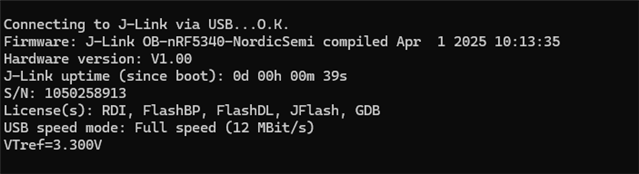
Below is the log from the attempted connection:
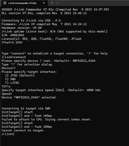
19:08:22.150	Selecting device with the serial number 000069661042
19:08:23.217	Error: Failed with exit code 1. Failed to device info one or more devices: * 69661042: [Probe] Device error: Failed to write DebugPort register 2: Unknown Error in J-Link DLL (error code =-1), code: Generic. Message: Operation device-info failed, [Probe] Device error: Failed to write DebugPort register 2: Unknown Error in J-Link DLL (error code =-1).
19:08:23.218	Selected device with the serial number 000069661042
19:08:23.218	Using nrfutil device to communicate with target via JLink
19:08:24.123	Reading readback protection status for Application core
19:08:24.123	Failed "reading readback protection status for application core". Error: code: 1, description: Generic, message: Batch task protection-get failed, [Probe] Device error: Failed to write DebugPort register 2: Unknown Error in J-Link DLL (error code =-1)
19:08:24.352	Error: Failed with exit code 1. One or more batch tasks failed: - [Probe] Device error: Failed to write DebugPort register 2: Unknown Error in J-Link DLL (error code =-1), code: Generic. Message: Batch task protection-get failed, [Probe] Device error: Failed to write DebugPort register 2: Unknown Error in J-Link DLL (error code =-1).
19:08:24.352	Error: Failed with exit code 1. One or more batch tasks failed: - [Probe] Device error: Failed to write DebugPort register 2: Unknown Error in J-Link DLL (error code =-1), code: Generic. Message: Batch task protection-get failed, [Probe] Device error: Failed to write DebugPort register 2: Unknown Error in J-Link DLL (error code =-1).
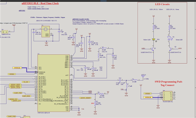
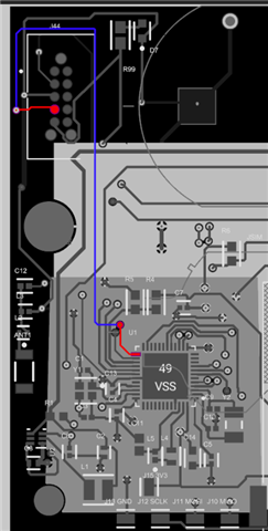
This is my current setup: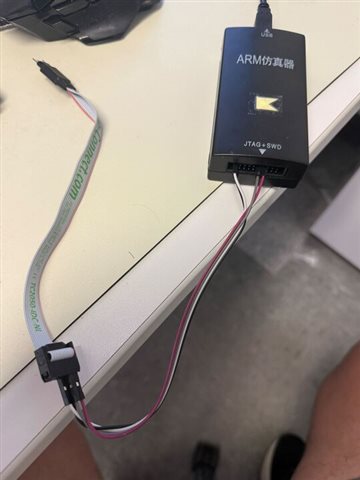
One thing that could improve is the length of the wires.
What might be the possible issues of my setup not working out?
Thank you,
Kevin