
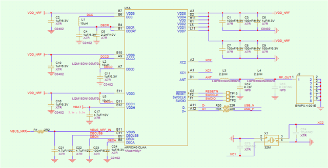
 I made a PCB board, but I couldn't connect to the chip with JLink. I used a lithium battery to power VDDH. I want to test if there is any problem with the hardware. I tried to measure the voltages of several regulators: VDDNRF = 1.8V, DECR = 1.09V, DECD = 1.106V, DECA = 1.245V, DECN = 1.0V. But I don't know what they should be under normal circumstances. I'm not sure if it's a hardware issue.
