This post is older than 2 years and might not be relevant anymore
More Info: Consider searching for newer posts

nrf52 UART pins

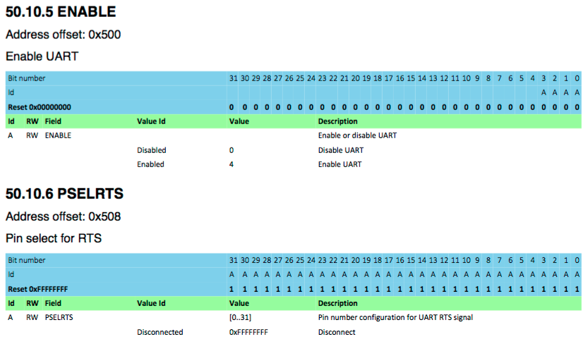
Hi, I am trying to figure out which GPIO pins i can use as UART on a nrf52 chip if i put it on a custom PCB (Not DK !!). From the reference manual (page 513, 48.10.7 and 48.10.9) it looks to me as if any (0 to 31) GPIO pin can be used as UART (as long as the corresponding pin is set in PSEL register and is not used by any other module), however i'm baffled with these tables and there seems to be very little explanation on how to actually read them. Any help ? Thanks !

  • You're correct, you can use any pin for UART. Here's a screenshot so we can talk about it:

    image description

    The id "A" in the leftmost column corresponds to the A below each bit number. If you look at the ENABLE register, only the lowest four bits have an A below them. What that's saying is that the ENABLE field in that register is only the lowest four bits. The other bits have no letter, and are thus opaque to you. They may be used for something internally and just undocumented, so it's good practice to not write to them.

    The PSELRTS field takes up the entire 32-bit register, as shown by an A underneath every bit. However, most of these bits will always be 0. You can see that valid values for the PSELRTS field are [0..31] (i.e., 0 through 31) and 0xFFFFFFFF. Any of the following lines would be valid:

    p_reg->PSELRTS = 4; // set to pin four
    p_reg->PSELRTS = 31; // set to pin thirty-one
    p_reg->PSELRTS = 0xFFFFFFFF; // disable
    

    If you write an invalid value (for example, 0xFFFFFFFE), then the behavior is undocumented and perhaps undefined.

    The rest of the stuff in the table: RW means readable and writeable, and Reset 0x00000000 tells you the default value when you reset the chip.

Related