application : ncs\v3.0.1\zephyr\samples\drivers\led\led_strip
Hi
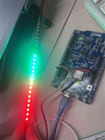
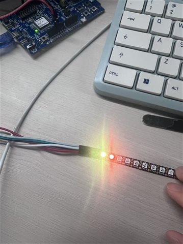
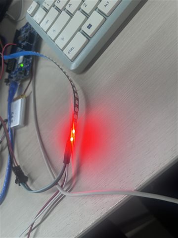
Recently, I have been working on development in NCS. I attempted to drive the WS2812B LED lights, but they failed to light up so far. I would like to ask you to check if there are any issues with the parameters and configurations. I successfully implemented the normal operation of the nrf52832 development board and the ws2812b LED driver in SDK 17.1.Therefore, I can confirm that my hardware is functioning properly.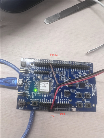
Here is the ws2812 pwm params on sdk17.1
#define WS2812_PIN NRF_GPIO_PIN_MAP(0,23)
// In each value, the most significant bit (15)determines the polarity of the output and theothers (14-0) compose the 15-bit value
#define WS2812_T1H 14 | 0x8000 //14ticks
#define WS2812_T0H 6 | 0x8000 //6ticks
#define LED_MATRIX_WIDTH 14
#define LED_MATRIX_HEIGHT 1
void pwm_init(void){
nrfx_pwm_config_t pwm_config = NRFX_PWM_DEFAULT_CONFIG;
pwm_config.output_pins[0] = NRFX_PWM_PIN_NOT_USED;
pwm_config.output_pins[1] = WS2812_PIN;
pwm_config.output_pins[2] = NRFX_PWM_PIN_NOT_USED;
pwm_config.output_pins[3] = NRFX_PWM_PIN_NOT_USED;
pwm_config.load_mode = NRF_PWM_LOAD_INDIVIDUAL;
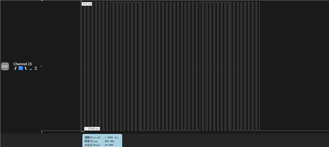
// WS2812 protocol requires a 800 kHz PWM frequency. PWM Top value = 20 and Base Clock = 16 MHz achieves this
pwm_config.top_value = 20;
pwm_config.base_clock = NRF_PWM_CLK_16MHz;
}Here is th spi config
nrf52dk_nrf52832.overlay
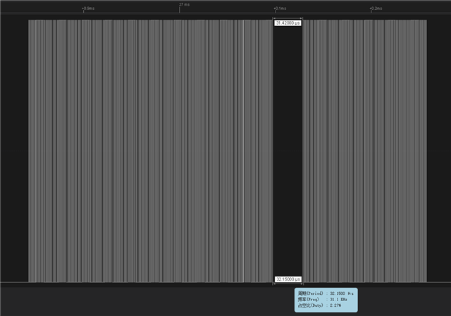
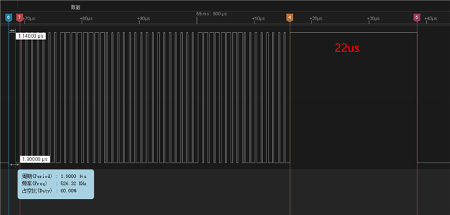
#define SPI_FREQ 2400000 //2.4Mhz = 0.42us
#define ZERO_FRAME 0x04 //100 means 0.42us"1" + 0.84"0"
#define ONE_FRAME 0x06 //110 means 0.84us"1" + 0.42"0"
&arduino_spi { /* MOSI on D11 / P0.23 */
compatible = "nordic,nrf-spim";
led_strip: ws2812@0 {
compatible = "worldsemi,ws2812-spi";
/* SPI */
reg = <0>; /* ignored, but necessary for SPI bindings */
spi-max-frequency = <SPI_FREQ>;
/* WS2812 */
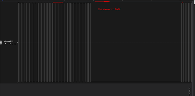
chain-length = <16>; /* arbitrary; change at will */
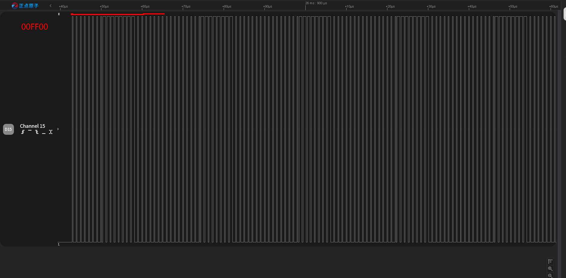
color-mapping = <LED_COLOR_ID_GREEN
LED_COLOR_ID_RED
LED_COLOR_ID_BLUE>;
spi-one-frame = <ONE_FRAME>;
spi-zero-frame = <ZERO_FRAME>;
};
};
/ {
aliases {
led-strip = &led_strip;
};
};
&pinctrl {
spi2_default: spi2_default {
group1 {
psels = <NRF_PSEL(SPIM_MOSI, 0, 23)>;
};
};
spi2_sleep: spi2_sleep {
group1 {
psels = <NRF_PSEL(SPIM_MOSI, 0 ,23)>;
low-power-enable;
};
};
}
prj.conf
CONFIG_LOG=y
CONFIG_LED_STRIP=y
CONFIG_LED_STRIP_LOG_LEVEL_DBG=y
# clock setting
CONFIG_CLOCK_CONTROL_NRF=y
CONFIG_CLOCK_CONTROL_NRF_K32SRC_RC=y
CONFIG_CLOCK_CONTROL_NRF_K32SRC_XTAL=n
CONFIG_CLOCK_CONTROL_NRF_K32SRC_RC_CALIBRATION=y
CONFIG_GPIO=y
main:
#define STRIP_NODE DT_ALIAS(led_strip)
#if DT_NODE_HAS_PROP(DT_ALIAS(led_strip), chain_length)
#define STRIP_NUM_PIXELS DT_PROP(DT_ALIAS(led_strip), chain_length)
#else
#error Unable to determine length of LED strip
#endif
#define DELAY_TIME K_MSEC(CONFIG_SAMPLE_LED_UPDATE_DELAY)
#define RGB(_r, _g, _b) { .r = (_r), .g = (_g), .b = (_b) }
static const struct led_rgb colors[] = {
RGB(0x0f, 0x00, 0x00), /* red */
RGB(0x00, 0x0f, 0x00), /* green */
RGB(0x00, 0x00, 0x0f), /* blue */
};
static struct led_rgb pixels[STRIP_NUM_PIXELS];
static const struct device *const strip = DEVICE_DT_GET(STRIP_NODE);
#define LED0_NODE DT_ALIAS(led0)
static const struct gpio_dt_spec led = GPIO_DT_SPEC_GET(LED0_NODE, gpios);
int main(void)
{
size_t color = 0;
int rc;
if (device_is_ready(strip)) {
LOG_INF("Found LED strip device %s", strip->name);
} else {
LOG_ERR("LED strip device %s is not ready", strip->name);
return 0;
}
if (!gpio_is_ready_dt(&led)) {
return 0;
}
rc = gpio_pin_configure_dt(&led, GPIO_OUTPUT_ACTIVE);
if (rc < 0) {
return 0;
}
LOG_INF("Displaying pattern on strip");
while (1) {
for (size_t cursor = 0; cursor < ARRAY_SIZE(pixels); cursor++) {
memset(&pixels, 0x00, sizeof(pixels));
memcpy(&pixels[cursor], &colors[color], sizeof(struct led_rgb));
rc = led_strip_update_rgb(strip, pixels, STRIP_NUM_PIXELS);
if (rc) {
LOG_ERR("couldn't update strip: %d", rc);
}
k_sleep(DELAY_TIME);
}
color = (color + 1) % ARRAY_SIZE(colors);
}
return 0;
}best regard