I'm a new software developer and I'm not a native English speaker. I ask questions through a translator now, the description might not be clear.
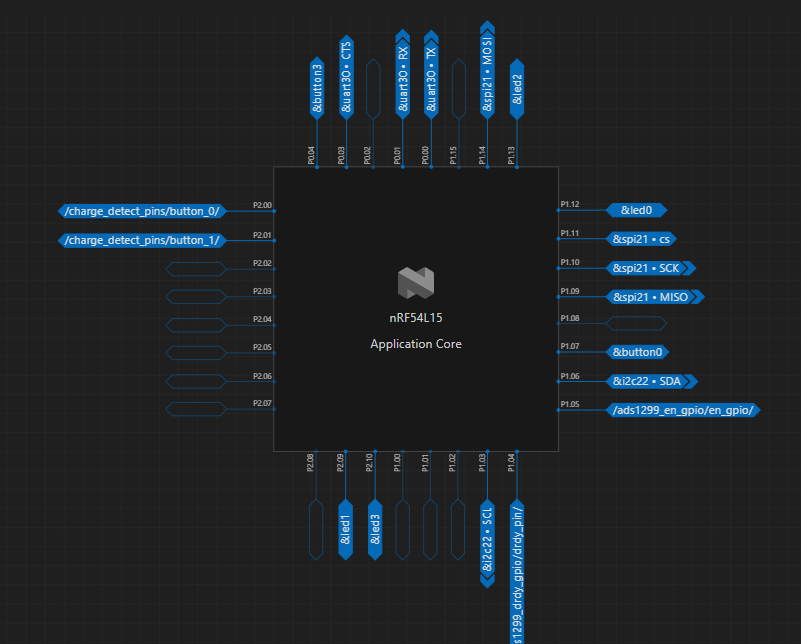
I am currently working on the NRF54L15. In my overlay file, I disabled UART20 and defined P1.05 as an enable pin for a peripheral. However, when the system powers on, there is still a high-pull operation on P1.05, just like for UART. I found that this operation occurs before the main function is executed because I added a delay at the first line of the main function and observed that the initial state of P1.05 was still high. After entering the main function, I can control the high and low levels of P1.05 as expected. I cannot allow P1.05 to be pulled high at the initial power-on because when the battery is low and charging, it will reset the NRF54L15, and the high pull on EN will drive a large load, preventing me from charging. I discovered that the high pull is bound to UART20, but I don't understand why it still occurs at the initial state of the program even though I overwrote it.
thanks
dts:
&uart20 {
status = "disabled";
};
&spi21 {
compatible = "nordic,nrf-spim";
status = "okay";
pinctrl-0 = <&spi21_default>;
pinctrl-1 = <&spi21_sleep>;
pinctrl-names = "default", "sleep";
cs-gpios = <&gpio1 11 GPIO_ACTIVE_LOW>;
};
&i2c22 {
compatible = "nordic,nrf-twim";
#address-cells = <1>;
#size-cells = <0>;
reg = <0xc8000 0x1000>;
interrupts = <200 NRF_DEFAULT_IRQ_PRIORITY>;
easydma-maxcnt-bits = <16>;
status = "okay";
zephyr,pm-device-runtime-auto;
clock-frequency = <100000>;
pinctrl-0 = <&i2c22_default>;
pinctrl-1 = <&i2c22_sleep>;
pinctrl-names = "default", "sleep";
bct24157l: bct24157l@2d {
compatible = "bosch,bct24157l";
reg = <0x2d>;
status = "okay";
};
};
&pinctrl {
spi21_default: spi21_default {
group1 {
psels = <NRF_PSEL(SPIM_SCK, 1, 10)>,
<NRF_PSEL(SPIM_MOSI, 1, 14)>,
<NRF_PSEL(SPIM_MISO, 1, 9)>;
};
};
spi21_sleep: spi21_sleep {
group1 {
psels = <NRF_PSEL(SPIM_SCK, 1, 10)>,
<NRF_PSEL(SPIM_MOSI, 1, 14)>,
<NRF_PSEL(SPIM_MISO, 1, 9)>;
};
};
i2c22_default: i2c22_default {
group1 {
psels = <NRF_PSEL(TWIM_SDA, 1, 6)>,
<NRF_PSEL(TWIM_SCL, 1, 3)>;
};
bias-pull-up;
drive-push-pull;
slew-rate-slow;
};
i2c22_sleep: i2c22_sleep {
group1 {
psels = <NRF_PSEL(TWIM_SDA, 1, 6)>,
<NRF_PSEL(TWIM_SCL, 1, 3)>;
};
bias-pull-up;
low-power-enable;
};
};
/delete-node/ &button1;
/delete-node/ &button2;
/delete-node/ &{/pin-controller/pwm20_default/group1/};
/delete-node/ &{/pin-controller/pwm20_sleep/group1/};
/delete-node/ &{/pin-controller/spi00_default/group1/};
/delete-node/ &{/pin-controller/spi00_sleep/group1/};
&spi00 {
/delete-property/ cs-gpios;
};
&gpio1 {
status = "okay";
};
&led0 {
gpios = <&gpio1 12 GPIO_ACTIVE_HIGH>;
label = "Start GPIO";
};
&led2 {
gpios = <&gpio1 13 GPIO_ACTIVE_LOW>;
label = "Reset GPIO";
};
&led3 {
gpios = <&gpio2 10 GPIO_ACTIVE_HIGH>;
label = "Charge LED";
};
&button0 {
gpios = <&gpio1 7 (GPIO_PULL_UP | GPIO_ACTIVE_LOW)>;
label = "Power Save Button";
zephyr,code = <INPUT_KEY_0>;
};
&uart30 {
status = "okay";
current-speed = <115200>;
pinctrl-0 = <&uart30_default>;
pinctrl-1 = <&uart30_sleep>;
pinctrl-names = "default", "sleep";
};
&pinctrl {
uart30_default: uart30_default {
group1 {
psels = <NRF_PSEL(UART_TX, 0, 0)>,
<NRF_PSEL(UART_RX, 0, 1)>;
};
};
uart30_sleep: uart30_sleep {
group1 {
psels = <NRF_PSEL(UART_TX, 0, 0)>,
<NRF_PSEL(UART_RX, 0, 1)>;
low-power-enable;
};
};
};
/ {
chosen {
zephyr,console = &uart30;
zephyr,shell-uart = &uart30;
zephyr,uart-mcumgr = &uart30;
zephyr,bt-mon-uart = &uart30;
zephyr,bt-c2h-uart = &uart30;
};
};
&led1 {
gpios = <&gpio2 9 0>;
};
/ {
ads1299_en_gpio {
compatible = "gpio-keys";
en_gpio {
gpios = <&gpio1 5 GPIO_ACTIVE_HIGH>;
label = "ADS1299 EN GPIO";
};
};
};
/ {
charge_detect_pins {
compatible = "gpio-keys";
button_0 {
gpios = <&gpio2 0 GPIO_ACTIVE_HIGH>;
label = "Charge Detect";
};
button_1 {
gpios = <&gpio2 1 GPIO_ACTIVE_HIGH>;
label = "Charge Status";
};
};
};
/ {
ads1299_drdy_gpio {
compatible = "gpio-keys";
drdy_pin {
gpios = <&gpio1 4 GPIO_ACTIVE_LOW>;
label = "ADS1299 DRDY";
};
};
};