GPIO P1.13 Edge Detection Causes High Floor Current on nRF54L15DK

## Description

On the nRF54L15DK, the measured floor current increases significantly when the GPIO is configured for button edge detection.

### Observed Behavior

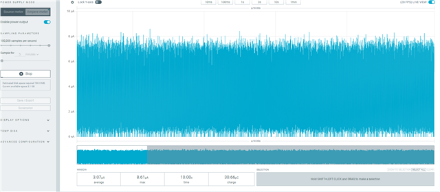
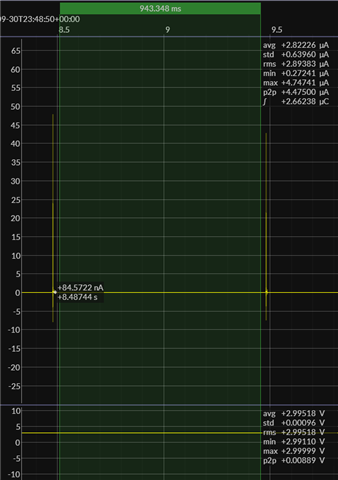
* Floor current baseline: ~4 µA (no button interrupt configured)
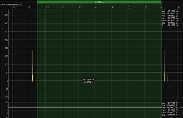
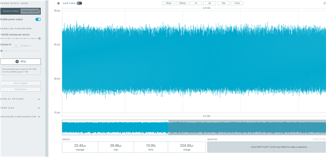
* Floor current after enabling GPIO P1.13 interrupt (edge detection for button): ~23 µA

### Expected Behavior

* Floor current should remain close to the baseline (~4 µA) regardless of button edge detection configuration.

---

## Steps to Reproduce

1. Configure GPIO pin for button input **without** interrupt → observe floor current (~4 µA).
2. Enable edge detection interrupt on the button GPIO → observe floor current (~23 µA).

---

## Device Tree Source

```dts
/* Direct motive, button device, button 0 */
gpio_button0: gpio_button {
compatible = "motive,button";
status = "okay";
gpios = <&gpio1 13 (GPIO_PULL_DOWN | GPIO_ACTIVE_HIGH)>;
};
```

## C Code

```c
/**
* @brief Enable button interrupt processing
* @param dev Device pointer
* @return 0 on success, negative error code on failure
*/
static int gpio_button_enable_impl(const struct device *dev)
{
struct gpio_button_data *data = dev->data;
const struct gpio_button_config *config = dev->config;
int ret;

atomic_set(&data->enabled, 1);

ret = gpio_pin_interrupt_configure(config->gpio_dev, config->pin,
GPIO_INT_EDGE_BOTH);
if (ret < 0) {
LOG_ERR("Failed to configure GPIO interrupt: %d", ret);
atomic_set(&data->enabled, 0);
return ret;
}

LOG_INF("Button enabled");
return 0;
}


/**
* @brief Initialize button device
* @param dev Device pointer
* @return 0 on success, negative error code on failure
*/
int gpio_button_init(const struct device *dev)
{
struct gpio_button_data *data = dev->data;
const struct gpio_button_config *config = dev->config;
int ret;

if (!device_is_ready(config->gpio_dev)) {
LOG_ERR("GPIO device not ready");
return -ENODEV;
}

/* Store device pointer for callbacks */
data->dev = dev;

/* Configure GPIO pin */
ret = gpio_pin_configure(config->gpio_dev, config->pin, config->flags);
if (ret < 0) {
LOG_ERR("Failed to configure GPIO pin: %d", ret);
return ret;
}

/* Initialize GPIO callback */
gpio_init_callback(&data->gpio_cb, _gpio_interrupt_handler, BIT(config->pin));
ret = gpio_add_callback(config->gpio_dev, &data->gpio_cb);
if (ret < 0) {
LOG_ERR("Failed to add GPIO callback: %d", ret);
return ret;
}

/* Initialize state */
atomic_set(&data->lastState, 0);
data->callback = _default_button_callback;
data->user_data = NULL;
data->pressStartTime = 0;
atomic_set(&data->enabled, 0);

LOG_INF("GPIO button initialized on pin %d", config->pin);
return 0;
}

```

---

## Impact

* Increases standby current consumption by nearly **6×**.
* May significantly reduce battery life in low-power operation.

Parents
  • Hi!

    Try adding this in a overlay:

    &gpio1 {
    sense-edge-mask = <(1 << 13)>;
    };

  • Hi Sigurd,

    Thanks for your reply. I tried your solution, but the floor current still remains around 23 µA. By the way, Motive is currently using SDK 3.0.0.

    Could you let me know what floor current you would expect when the GPIO is configured for both-edge interrupt?

  • Hi!

    I'm testing this using this as a starting-point: https://github.com/nrfconnect/sdk-nrf/tree/main/tests/benchmarks/current_consumption/gpio_idle

    I'm using NCS 3.1.0 , with nRF54L15-DK v1.0.0

    1) 

    In nrf54l15dk_nrf54l15_cpuapp.overlay I change:

    gpios = <&gpio1 5 (GPIO_PULL_UP | GPIO_ACTIVE_LOW)>;
     
    to
    gpios = <&gpio1 13 (GPIO_PULL_DOWN  | GPIO_ACTIVE_HIGH)>;
    2)
    In main.c, I change 
    ret = gpio_pin_interrupt_configure(sw.port, sw.pin, GPIO_INT_LEVEL_ACTIVE);
    to
    ret = gpio_pin_interrupt_configure(sw.port, sw.pin, GPIO_INT_EDGE_BOTH);
    3)
    When measuring the current, I get the same as you, around ~22uA:
     

    4)

    I then add  sense-edge-mask = <(1 << 13)>; to the gpio1 dts node, so it looks like this in the overlay:

    &gpio1 {
        status = "okay";
        sense-edge-mask = <(1 << 13)>;
    };
    I measure again, and I see it have dropped to ~3 uA
  • Hi Sigurd,

    Awesome! Your solution worked for me, though I made a small change. Could you explain why this issue is resolved and if there are any potential problems I should be aware of?

    @ src/embedded/bc_hbii/ble_beacon_v2_nrf54l/boards/motive/beacon_v2_overlay/beacon_v2_nrf54l15_cpuapp-dk.overlay:64 @
        ...
        /* Direct motive,button device, button 0 */
        gpio_button0: gpio_button {
            compatible = "motive,button";
            status = "okay";
            gpios = <&gpio1 13 (GPIO_PULL_UP | GPIO_ACTIVE_LOW)>;
        };
    };
    
    &gpio1 {
        status = "okay";
        sense-edge-mask = <(1 << 13)>;
    };

  • Hi!

    1)

    So you changed from

    (GPIO_PULL_DOWN | GPIO_ACTIVE_HIGH)

    to

    (GPIO_PULL_UP | GPIO_ACTIVE_LOW)

    What is "correct" here depends on your PCB and how the button is designed to be connected to when the button in pressed. On our DK's, the button-pin is connected to ground when the button is pressed, therefore "(GPIO_PULL_UP | GPIO_ACTIVE_LOW)" is correct for the DK.

    2)

    With this sense-edge-mask, we now use Port event instead of IN event.  PORT events are lower-power.

    You can read more about this here: https://docs.nordicsemi.com/bundle/ps_nrf54L15/page/gpiote.html

  • Hi Sigurd,

    Thanks for your explanation. I have a system design question regarding port events.
    In our system, the nRF54L15 needs to handle three types of interrupts: the nPM2100 host interrupt, the RTC alarm interrupt, and a GPIO button interrupt on GPIO port 1.
    If I use a port event, do I need to determine which specific pin triggered the interrupt?

    For example, do all of these need to share the same _gpiote_port_isr_cb, or can they each use separate ISR callbacks?


    int init_sources(void)
    {
        int ret;
    
        /* Configure PMIC INT as input with pull-up, level-low interrupt */
        if (!device_is_ready(pmicInt.port)) {
            return -ENODEV;
        }
        ret = gpio_pin_configure_dt(&pmicInt, GPIO_INPUT | GPIO_PULL_UP);
        if (ret) {
            return ret;
        }
        ret = gpio_pin_interrupt_configure_dt(&pmicInt, GPIO_INT_LEVEL_LOW);
        if (ret) {
            return ret;
        }
    
        /* Configure RTC alarm: input with appropriate pull, edge to active */
        if (!device_is_ready(rtcInt.port)) {
            return -ENODEV;
        }
        ret = gpio_pin_configure_dt(&rtcInt, GPIO_INPUT |
                                              ((rtcInt.dt_flags & GPIO_PULL_UP) ? GPIO_PULL_UP : 0) |
                                              ((rtcInt.dt_flags & GPIO_PULL_DOWN) ? GPIO_PULL_DOWN : 0));
        if (ret) {
            return ret;
        }
        ret = gpio_pin_interrupt_configure_dt(&rtcInt, GPIO_INT_EDGE_TO_ACTIVE);
        if (ret) {
            return ret;
        }
    
        /* Configure Button: input with pull, edge-both for wake + software debounce */
        if (!device_is_ready(btn0.port)) {
            return -ENODEV;
        }
        ret = gpio_pin_configure_dt(&btn0, GPIO_INPUT |
                                           ((btn0.dt_flags & GPIO_PULL_UP) ? GPIO_PULL_UP : 0) |
                                           ((btn0.dt_flags & GPIO_PULL_DOWN) ? GPIO_PULL_DOWN : 0));
        if (ret) {
            return ret;
        }
        ret = gpio_pin_interrupt_configure_dt(&btn0, GPIO_INT_EDGE_BOTH);
        if (ret) {
            return ret;
        }
    
        ...
    
        /* Register one PORT callback on a representative port device.
         * On nRF54, pins for different ports reside on different GPIO devs.
         * We add callback to *each* unique port used by our lines.
         */
        gpio_init_callback(&gpiotePortCb, _gpiote_port_isr_cb, 0);
    
        /* Add callback to ports actually used */
        ret = gpio_add_callback(pmicInt.port, &gpiotePortCb);
        if (ret) {
            return ret;
        }
        if (rtcInt.port != pmicInt.port) {
            ret = gpio_add_callback(rtcInt.port, &gpiotePortCb);
            if (ret) {
                return ret;
            }
        }
        if (btn0.port != pmicInt.port && btn0.port != rtcInt.port) {
            ret = gpio_add_callback(btn0.port, &gpiotePortCb);
            if (ret) {
                return ret;
            }
        }
    
        return 0;
    }
    
    
    static void _gpiote_port_isr_cb(const struct device *port, struct gpio_callback *cb,
                                    gpio_port_pins_t pins)
    {
        ARG_UNUSED(cb);
    
        /* Check which known pins are toggled/active on this port and set flags.
         * Keep ISR tiny: just set flags and schedule work/debounce.
         */
    
        /* PMIC: level-low -> if asserted (read pin == 0), set flag */
        if (port == pmicInt.port) {
            int val = gpio_pin_get(port, pmicInt.pin);
            if (val == 0) {
                atomic_or(&wakeFlags, WAKE_CAUSE_PMIC);
                k_work_submit(&pmicWork);
            }
        }
    
        /* RTC: edge-to-active -> we treat any interrupt as a cause */
        if (port == rtcInt.port) {
            /* We don't need to read the pin; a pulse already triggered this ISR */
            atomic_or(&wakeFlags, WAKE_CAUSE_RTC);
            k_work_submit(&rtcWork);
        }
    
        /* Button: edge-both -> start/restart debounce window */
        if (port == btn0.port) {
            atomic_or(&wakeFlags, WAKE_CAUSE_BUTTON);
            (void)k_work_reschedule(&btnDebounceWork, K_MSEC(BTN_DEBOUNCE_MS));
        }
    
        /* Record snapshot for quick diagnostics outside ISR */
        lastWakeSnapshot = atomic_get(&wakeFlags);
    }


Reply
  • Hi Sigurd,

    Thanks for your explanation. I have a system design question regarding port events.
    In our system, the nRF54L15 needs to handle three types of interrupts: the nPM2100 host interrupt, the RTC alarm interrupt, and a GPIO button interrupt on GPIO port 1.
    If I use a port event, do I need to determine which specific pin triggered the interrupt?

    For example, do all of these need to share the same _gpiote_port_isr_cb, or can they each use separate ISR callbacks?


    int init_sources(void)
    {
        int ret;
    
        /* Configure PMIC INT as input with pull-up, level-low interrupt */
        if (!device_is_ready(pmicInt.port)) {
            return -ENODEV;
        }
        ret = gpio_pin_configure_dt(&pmicInt, GPIO_INPUT | GPIO_PULL_UP);
        if (ret) {
            return ret;
        }
        ret = gpio_pin_interrupt_configure_dt(&pmicInt, GPIO_INT_LEVEL_LOW);
        if (ret) {
            return ret;
        }
    
        /* Configure RTC alarm: input with appropriate pull, edge to active */
        if (!device_is_ready(rtcInt.port)) {
            return -ENODEV;
        }
        ret = gpio_pin_configure_dt(&rtcInt, GPIO_INPUT |
                                              ((rtcInt.dt_flags & GPIO_PULL_UP) ? GPIO_PULL_UP : 0) |
                                              ((rtcInt.dt_flags & GPIO_PULL_DOWN) ? GPIO_PULL_DOWN : 0));
        if (ret) {
            return ret;
        }
        ret = gpio_pin_interrupt_configure_dt(&rtcInt, GPIO_INT_EDGE_TO_ACTIVE);
        if (ret) {
            return ret;
        }
    
        /* Configure Button: input with pull, edge-both for wake + software debounce */
        if (!device_is_ready(btn0.port)) {
            return -ENODEV;
        }
        ret = gpio_pin_configure_dt(&btn0, GPIO_INPUT |
                                           ((btn0.dt_flags & GPIO_PULL_UP) ? GPIO_PULL_UP : 0) |
                                           ((btn0.dt_flags & GPIO_PULL_DOWN) ? GPIO_PULL_DOWN : 0));
        if (ret) {
            return ret;
        }
        ret = gpio_pin_interrupt_configure_dt(&btn0, GPIO_INT_EDGE_BOTH);
        if (ret) {
            return ret;
        }
    
        ...
    
        /* Register one PORT callback on a representative port device.
         * On nRF54, pins for different ports reside on different GPIO devs.
         * We add callback to *each* unique port used by our lines.
         */
        gpio_init_callback(&gpiotePortCb, _gpiote_port_isr_cb, 0);
    
        /* Add callback to ports actually used */
        ret = gpio_add_callback(pmicInt.port, &gpiotePortCb);
        if (ret) {
            return ret;
        }
        if (rtcInt.port != pmicInt.port) {
            ret = gpio_add_callback(rtcInt.port, &gpiotePortCb);
            if (ret) {
                return ret;
            }
        }
        if (btn0.port != pmicInt.port && btn0.port != rtcInt.port) {
            ret = gpio_add_callback(btn0.port, &gpiotePortCb);
            if (ret) {
                return ret;
            }
        }
    
        return 0;
    }
    
    
    static void _gpiote_port_isr_cb(const struct device *port, struct gpio_callback *cb,
                                    gpio_port_pins_t pins)
    {
        ARG_UNUSED(cb);
    
        /* Check which known pins are toggled/active on this port and set flags.
         * Keep ISR tiny: just set flags and schedule work/debounce.
         */
    
        /* PMIC: level-low -> if asserted (read pin == 0), set flag */
        if (port == pmicInt.port) {
            int val = gpio_pin_get(port, pmicInt.pin);
            if (val == 0) {
                atomic_or(&wakeFlags, WAKE_CAUSE_PMIC);
                k_work_submit(&pmicWork);
            }
        }
    
        /* RTC: edge-to-active -> we treat any interrupt as a cause */
        if (port == rtcInt.port) {
            /* We don't need to read the pin; a pulse already triggered this ISR */
            atomic_or(&wakeFlags, WAKE_CAUSE_RTC);
            k_work_submit(&rtcWork);
        }
    
        /* Button: edge-both -> start/restart debounce window */
        if (port == btn0.port) {
            atomic_or(&wakeFlags, WAKE_CAUSE_BUTTON);
            (void)k_work_reschedule(&btnDebounceWork, K_MSEC(BTN_DEBOUNCE_MS));
        }
    
        /* Record snapshot for quick diagnostics outside ISR */
        lastWakeSnapshot = atomic_get(&wakeFlags);
    }


Children
  • Hi!

    smith.hu said:

    If I use a port event, do I need to determine which specific pin triggered the interrupt?

    No, the underlaying GPIO driver will do that for you.

    smith.hu said:
    For example, do all of these need to share the same _gpiote_port_isr_cb, or can they each use separate ISR callbacks?

    On the application level, you can have seperate callbacks for each pin

Related