
Hello all !
I'm currently trying to make a scan with our custom board, I've made a custom board with our GPIO and the use of the SPI4 instead of QSPI for the 7002 -> 5340 communication, we also use the CDC ACM USB to use direct USB connection for debug and terminal print / command.
In the scan project we have the main.c, in this main there is no indication of how the device is powered up (supply / IOVDD / BUCK EN), if I'm understanding correctly we are setting those up in the device three with the overlay / board configuration file :
/dts-v1/;
#include <nordic/nrf5340_cpuappns_qkaa.dtsi>
#include "RoomzDisplay-pinctrl.dtsi"
#include <zephyr/dt-bindings/input/input-event-codes.h>

/ {
	model = "Roomz Display HW 3.1 (CPUAPP Non-Secure)";
	compatible = "ROOMZ,RoomzDisplay-cpuapp-ns";

	chosen {
		zephyr,sram = &sram0_ns;
		zephyr,flash = &flash0;
		zephyr,code-partition = &slot0_ns_partition;
		zephyr,console = &uart0;
		zephyr,shell-uart = &uart0;
		zephyr,uart-mcumgr = &uart0;
		zephyr,bt-mon-uart = &uart0;
		zephyr,bt-c2h-uart = &uart0;
		zephyr,wifi = &wlan0;
	};

	/* Power Control GPIOs */
	power-gpios {
		compatible = "gpio-leds";

		pwr_3v3_enable: pwr-3v3-enable {
			gpios = <&gpio1 12 0>;
			label = "3V3 Power Enable";
		};

		pwr_ite_flash_oe: pwr-ite-flash-oe {
			gpios = <&gpio1 11 GPIO_ACTIVE_HIGH>;
			label = "ITE Flash Output Enable";
		};

		pwr_ite_enable: pwr-ite-enable {
			gpios = <&gpio0 2 GPIO_ACTIVE_HIGH>;
			label = "ITE Enable";
		};

		pwr_nfc_enable: pwr-nfc-enable {
			gpios = <&gpio1 5 GPIO_ACTIVE_HIGH>;
			label = "NFC Enable";
		};
	};

	/* Status/Monitor GPIOs */
	status-gpios {
		compatible = "gpio-keys";

		tps_status: tps-status {
			gpios = <&gpio0 28 (GPIO_PULL_UP | GPIO_ACTIVE_HIGH)>;
			label = "TPS Status";
		};

		pmic_pwrgood: pmic-pwrgood {
			gpios = <&gpio1 7 GPIO_ACTIVE_HIGH>;
			label = "PMIC Power Good";
		};

		ite_ready: ite-ready {
			gpios = <&gpio0 24 (GPIO_PULL_UP | GPIO_ACTIVE_HIGH)>;
			label = "ITE Ready Status";
		};
	};

	/* Reset/Control GPIOs */
	control-gpios {
		compatible = "gpio-leds";

		ite_reset: ite-reset {
			gpios = <&gpio1 15 GPIO_ACTIVE_LOW>;
			label = "ITE Reset";
		};

		msp_reset: msp-reset {
			gpios = <&gpio1 8 GPIO_ACTIVE_LOW>;
			label = "MSP430 Reset";
		};

		msp_test: msp-test {
			gpios = <&gpio0 27 GPIO_ACTIVE_HIGH>;
			label = "MSP430 Test Pin";
		};

		msp_wakeup: msp-wakeup {
			gpios = <&gpio1 13 GPIO_ACTIVE_HIGH>;
			label = "MSP430 Wakeup";
		};
	};

	/* Interrupt/Wakeup GPIOs */
	wakeup-gpios {
		compatible = "gpio-keys";

		nfc_wakeup: nfc-wakeup {
			gpios = <&gpio1 1 (GPIO_PULL_UP | GPIO_ACTIVE_LOW)>;
			label = "NFC Wakeup";
		};

		bootloader_backdoor: bootloader-backdoor {
			gpios = <&gpio1 4 (GPIO_PULL_UP | GPIO_ACTIVE_LOW)>;
			label = "Bootloader Backdoor";
		};
	};

	/* Aliases for compatibility */
	aliases {
		watchdog0 = &wdt0;
		i2c-0 = &i2c1;
		/* Power Control Aliases */
		pwr-3v3-enable = &pwr_3v3_enable;
		pwr-ite-enable = &pwr_ite_enable;
		pwr-nfc-enable = &pwr_nfc_enable;
		/* Control GPIO Aliases */
		ite-reset = &ite_reset;
		msp-reset = &msp_reset;
		msp-wakeup = &msp_wakeup;
	};
};

#include "RoomzDisplay-cpuapp_partitioning.dtsi"
#include "RoomzDisplay-shared_sram.dtsi"

/* GPIO Controllers */
&gpiote {
	status = "okay";
};

&gpio0 {
	status = "okay";
};

&gpio1 {
	status = "okay";
};

/* ADC configuration for battery voltage monitoring */
&adc {
	status = "okay";
	#address-cells = <1>;
	#size-cells = <0>;

	channel@0 {
		reg = <0>;
		zephyr,gain = "ADC_GAIN_1_6";
		zephyr,reference = "ADC_REF_INTERNAL";
		zephyr,acquisition-time = <0>;
		zephyr,input-positive = <NRF_SAADC_AIN0>; /* P0.04 */
		zephyr,resolution = <12>;
	};
};

/* I2C1 - Main I2C Bus */
&i2c1 {
	compatible = "nordic,nrf-twim";
	status = "okay";
	clock-frequency = <I2C_BITRATE_STANDARD>;
	pinctrl-0 = <&i2c1_default>;
	pinctrl-1 = <&i2c1_sleep>;
	pinctrl-names = "default", "sleep";
};

/* UART0 - Debug/Console */
&uart0 {
	status = "okay";
	current-speed = <115200>;
	pinctrl-0 = <&uart0_default>;
	pinctrl-1 = <&uart0_sleep>;
	pinctrl-names = "default", "sleep";
};

/* UART1 - MSP430 BSL Interface */
&uart1 {
	compatible = "nordic,nrf-uarte";
	status = "okay";
	current-speed = <9600>;
	pinctrl-0 = <&uart1_default>;
	pinctrl-1 = <&uart1_sleep>;
	pinctrl-names = "default", "sleep";
};

/* SPI2 - ITE Interface (Using SPI2 to avoid conflict with UART0) */
&spi2 {
	compatible = "nordic,nrf-spim";
	status = "okay";
	pinctrl-0 = <&spi2_default>;
	pinctrl-1 = <&spi2_sleep>;
	pinctrl-names = "default", "sleep";
	cs-gpios = <&gpio0 25 GPIO_ACTIVE_LOW>;
	max-frequency = <DT_FREQ_M(8)>;
};

/* SPI3 - ITE Flash Interface (Manual CS control) */
&spi3 {
	compatible = "nordic,nrf-spim";
	status = "okay";
	pinctrl-0 = <&spi3_default>;
	pinctrl-1 = <&spi3_sleep>;
	pinctrl-names = "default", "sleep";
	/* No cs-gpios - CS controlled manually via GPIO */
};

/* SPI4 - nRF7002 WiFi Module */
&spi4 {
	compatible = "nordic,nrf-spim";
	status = "okay";
	pinctrl-0 = <&spi4_default>;
	pinctrl-1 = <&spi4_sleep>;
	pinctrl-names = "default", "sleep";
	cs-gpios = <&gpio0 11 GPIO_ACTIVE_LOW>;

	nrf70: nrf7002@0 {
		compatible = "nordic,nrf7002-spi";
		status = "okay";
		reg = <0>;
		spi-max-frequency = <8000000>;

		/* nRF7002 Control GPIOs */
		iovdd-ctrl-gpios = <&gpio1 0 GPIO_ACTIVE_HIGH>;
		bucken-gpios = <&gpio0 12 GPIO_ACTIVE_HIGH>;
		host-irq-gpios = <&gpio0 19 GPIO_ACTIVE_HIGH>;

		/* WiFi TX power settings (in dBm) */
		wifi-max-tx-pwr-2g-dsss = <21>;
		wifi-max-tx-pwr-2g-mcs0 = <16>;
		wifi-max-tx-pwr-2g-mcs7 = <16>;
		wifi-max-tx-pwr-5g-low-mcs0 = <9>;
		wifi-max-tx-pwr-5g-low-mcs7 = <9>;
		wifi-max-tx-pwr-5g-mid-mcs0 = <11>;
		wifi-max-tx-pwr-5g-mid-mcs7 = <11>;
		wifi-max-tx-pwr-5g-high-mcs0 = <13>;
		wifi-max-tx-pwr-5g-high-mcs7 = <13>;

		wlan0: wlan {
			compatible = "nordic,wlan";
		};

		supply-gpios = <&gpio1 12 0>;
	};
};

/* QSPI - External Flash */
&qspi {
	status = "okay";
	pinctrl-0 = <&qspi_default>;
	pinctrl-1 = <&qspi_sleep>;
	pinctrl-names = "default", "sleep";

	mx25r64: mx25r6435f@0 {
		compatible = "nordic,qspi-nor";
		reg = <0>;
		writeoc = "pp4io";
		readoc = "read4io";
		sck-frequency = <8000000>;
		jedec-id = [c2 28 17];
		sfdp-bfp = [
			e5 20 f1 ff  ff ff ff 03  44 eb 08 6b  08 3b 04 bb
			ee ff ff ff  ff ff 00 ff  ff ff 00 ff  0c 20 0f 52
			10 d8 00 ff  23 72 f5 00  82 ed 04 cc  44 83 68 44
			30 b0 30 b0  f7 c4 d5 5c  00 be 29 ff  f0 d0 ff ff
		];
		size = <67108864>;
		has-dpd;
		t-enter-dpd = <10000>;
		t-exit-dpd = <35000>;
	};
};

/* USB Device */
zephyr_udc0: &usbd {
	compatible = "nordic,nrf-usbd";
	status = "okay";
};
And my overlay files for the CDC ACM
/ {
chosen {
zephyr,console = &cdc_acm_uart0;
zephyr,shell-uart = &cdc_acm_uart0;
};
};
&zephyr_udc0 {
cdc_acm_uart0: cdc_acm_uart0 {
compatible = "zephyr,cdc-acm-uart";
};
};
&i2c1 {
clock-frequency = <I2C_BITRATE_STANDARD>;
};
&mx25r64 {
sck-frequency = <DT_FREQ_M(32)>;
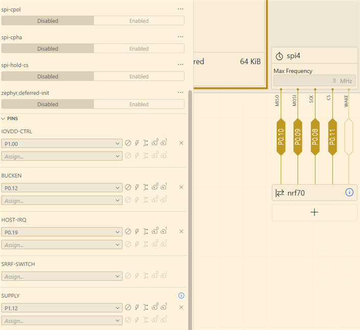
};For now I can build and program my board but I see that the power supply, io vdd and bucken is not enable, do we need to enable this on our side ? Or the device three with device 7002 on SPI4 with the given pin make this automatic, like in the pictures bellow :
There is also the board yml files, we add our two chips we use on board as in the 7002 DK board on the NCS :
board:
  name: RoomzDisplay
  vendor: ROOMZ
  socs:
  - name: nrf5340
    variants:
    - name: ns
      cpucluster: cpuapp
    - name: nrf7001
      cpucluster: cpuapp
      variants:
      - name: ns
Best regards,
Valentin Künti

