Hey Nordic Team
Just looking for guidance and clarification on the nPM1300 setup. couple of questions on the sample setup below.
Project Overview
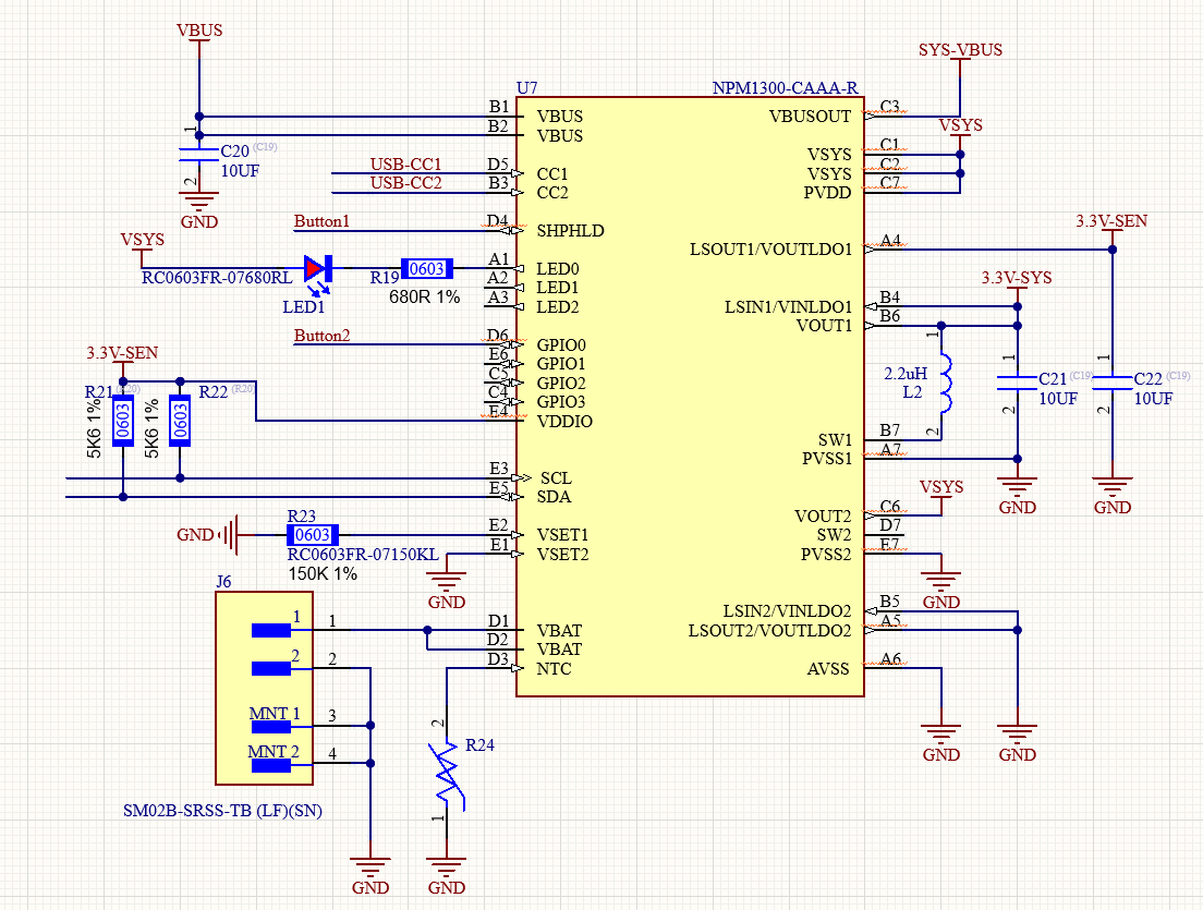
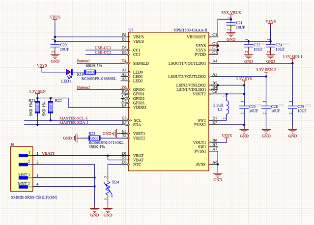
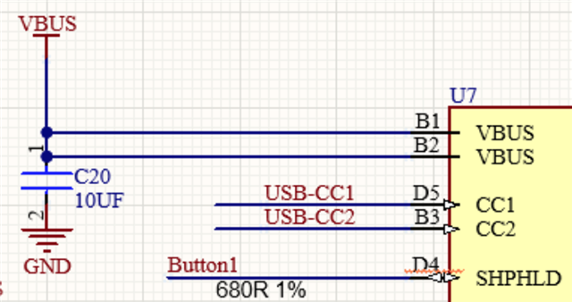
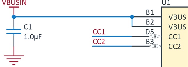
Project is a consumer grade hand held device that charges with USB C or USB 2 connection with a 3.7v Li ion battery and couple of buttons, the current requirements is well within the specifications of the LDO of the nPm1300 chip so that's fine, Im unclear of the output setup to the rest of the system.
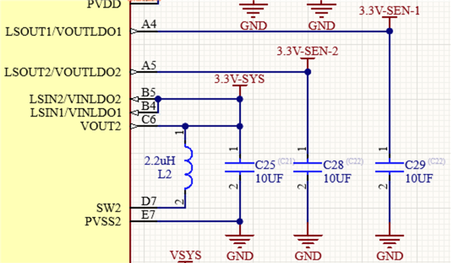
I am using a nrf5340 as the Soc and couple of analog and i2c sensors, My plan is to power the Soc off the "3.3V-SYS" rail and the rest of the sensors on the "3.3V-SEN rail" the idea is to be able to turn the sensors on and off via the LDO switch in software when powered down.
1) Does this make sense for best shutdown setup and current consumption monitoring ? My initial thought was that the VSYS output would be regulated and the LDO 1 and 2 could be used independently but it does not seem like that's the case.
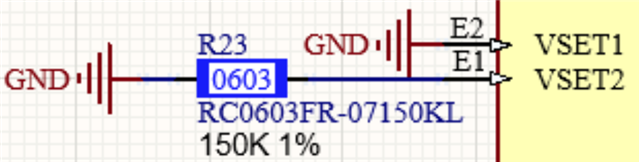
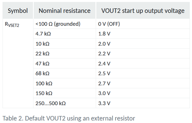
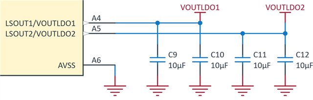
2) I know the LDO outputs can be setup via the registers but since the SOC will be powered on boot by LDO1 how do I set the boot up voltage to 3v3? The datasheet notes the max as 2.7V for LDO1 ?
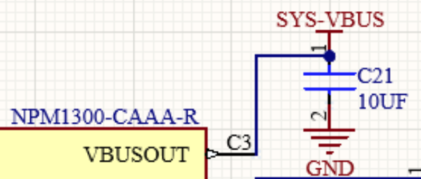
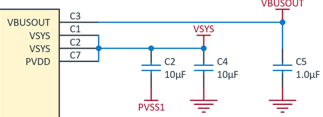
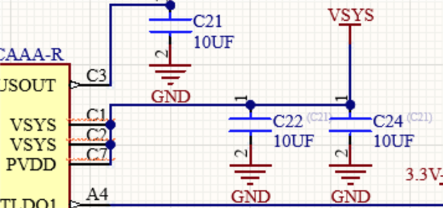
3) If the above is correct do I just leave VSYS and SYS-VBUS unconnected/used ?