nRF54L15 power on crystal load capacitor selection

Hi

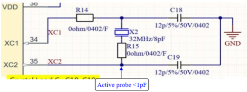
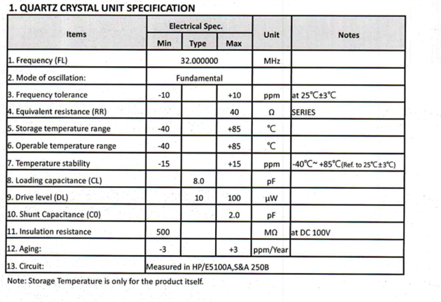
I have some questions regarding the 32 MHz crystal on the nRF54L15:

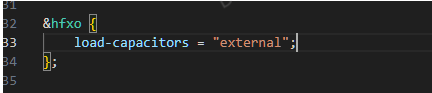
  1. If my firmware is configured to use external capacitors, will the very first crystal startup waveform captured after power-on already be using the external capacitors? Or is it still using the internal capacitors at that moment?

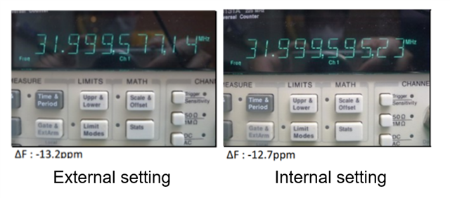
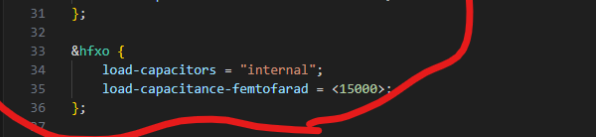
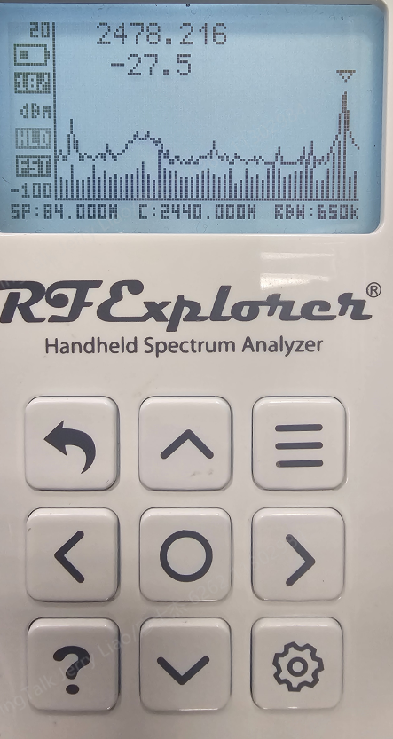
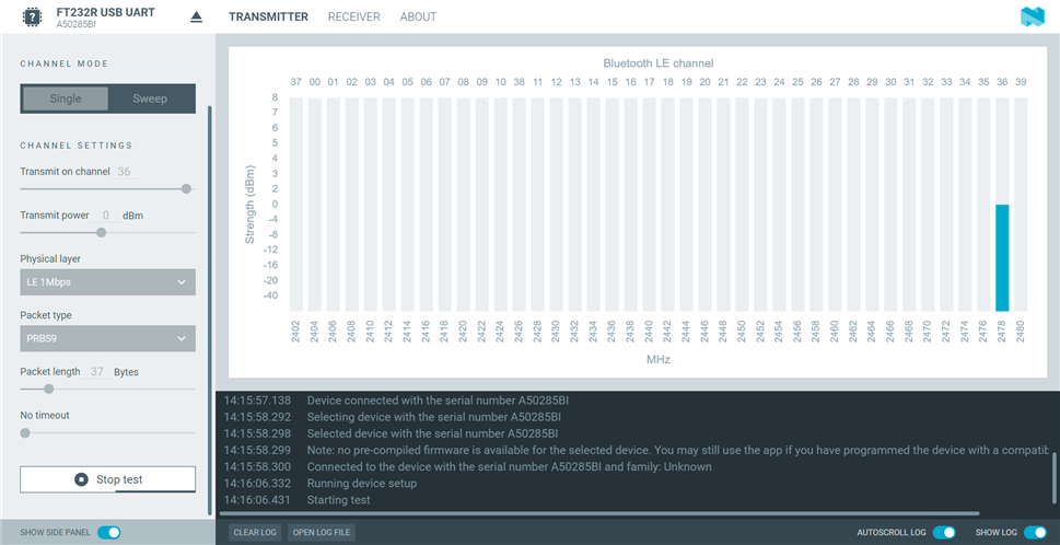
  2. The reason I’m asking is that I used the same PCB design but tested it with different firmware settings (external vs. internal capacitors). The measured frequency offset did not match my expectations. My external load capacitors are 12 pF, and the internal setting is the default 15 pF. However, the result I observed is that when using only the external capacitors, the frequency offset is actually 2 ppm slower compared to using the internal capacitors in firmware (with the external capacitors still mounted).

Parents
  • Hi,

    That is unexpected. A too high frequency indicate too low load capacitor value, and vise versa. How do you measure this? The recommended way to measure is to set up a carrier frequency (I suggest you use the radio test sample) and measure the offset using a signal/spectrum analyzer).

    At startup, the HFINT is used by default, and the HFXO is only started by firmware when an accurate clock is needed. And when the HFXO is started, the configured values for load capacitors are used from the start.

    Which 32MHz crystal are you using? Can you share the datasheet? Also, how does your devicetree where you configure the load capacitors look like?

    For reference using internal, it should look like this which is the default as you write (here with 15 pF, adjust value as needed):

    &hfxo {
    	load-capacitors = "internal";
    	load-capacitance-femtofarad = <15000>;
    };

    Disabling internal can be done like this:

    &hfxo {
          load-capacitors = "external";
    };

Reply
  • Hi,

    That is unexpected. A too high frequency indicate too low load capacitor value, and vise versa. How do you measure this? The recommended way to measure is to set up a carrier frequency (I suggest you use the radio test sample) and measure the offset using a signal/spectrum analyzer).

    At startup, the HFINT is used by default, and the HFXO is only started by firmware when an accurate clock is needed. And when the HFXO is started, the configured values for load capacitors are used from the start.

    Which 32MHz crystal are you using? Can you share the datasheet? Also, how does your devicetree where you configure the load capacitors look like?

    For reference using internal, it should look like this which is the default as you write (here with 15 pF, adjust value as needed):

    &hfxo {
    	load-capacitors = "internal";
    	load-capacitance-femtofarad = <15000>;
    };

    Disabling internal can be done like this:

    &hfxo {
          load-capacitors = "external";
    };

Children
  • Hi Einar,

    1. Our test setup uses a frequency counter (Agilent 53131A) and an active probe (Tektronix P6243) to measure the crystal frequency. The firmware we are using is based on nRF Connect SDK v3.0.0 – direct_test_mode, with the only modification being the setting to use either the external capacitor or the internal capacitor.

    2. So can I conclude that when I measure the HFXO signal at the C19 node, the load-capacitor configuration is already active at that moment.

    3.  Based on what I found in a forum discussion about capacitor selection, one of the replies mentioned that “the external capacitors are also physically present in parallel with the internal capacitors.”

    Because of this, I assumed that when using the internal 15 pF setting, the internal capacitor would be in parallel with my external 12 pF capacitors, giving a total of around 27 pF.
    Following this logic, when testing on the same PCB (which always has 12 pF external capacitors), the internal-cap setting should give a slower frequency than the external-cap setting.

    However, in our actual measurements, both configurations show almost the same behavior, with an effective load close to 13 pF. This is still within the spec, but it is different from what we expected.
    You can refer to the figure below.

     nRF54L15 crystal load capacitor selection 

    4. We are using the X2C032000B81H-HS/HELE crystal, and the load capacitors are shown in the schematic above.

    5.I confirmed with our FW engineer that the configuration is the same as the information you provided, as shown below.

  • Hi,

    I am having problems understanding how there can be so little frequency difference when using both internal and external caps, compared to only external. Can you double check that the generated .zephyr in the build folder actually has the configured values when you test both with and without external caps? It could also be interesting to read back XOSC32M.CONFIG.INTCAP using "nrfutil device read --address 0x5012071C --direct" to see that this is actually used.

    I do not see a problem with the measurement setup you have described, but as the resuls are unexpected, I wonder if you can also test with a signal/spectrum analyzer, and check the frequency accuracy of a carrier using the radio test as mentioned in my previous post? (Similarly to what is described in the Crystal Oscillator Design Considerations white paper).

  • Hi Einar,

    I tested two different firmware versions under conditions with and without the external 12 pF load capacitance, and recorded the value at address 0x5012071C along with the TX frequency, as shown in the table below. From the results, it appears that the setting is taking effect. However, I would like to confirm whether the value 0x0000002B represents 15 pF.
    I have also attached photos of the handheld spectrum analyzer and the DTM configuration used during the test.

    By the way, I read the register value on our PCB using the DK with the command nrfjprog --memrd 0x5012071C.

    PCB capacitor  PCB1 with 12pf PCB1 without 12pf
    FW Internal cap External cap Internal cap External cap
    Tx frequency 2478.216 2478.216 2478.216 2478.216
    Tx Power -27.5 -27 -29.5 -29.5
    Read 0x5012071C "0000002B "00000000 "0000002B "00000000

  • Hi,

    An INTCAP value of 0x2B looks sensible and can match 15 pF. (The exact value of the  register can vary between devices, as trim values are used in the calculation).

    I am not sure if we can trust the measurement here, though? It is very difficult to see that you can have the same Tx frequency with so big difference in load capacitance. If I read this correctly, you get the same with no load caps, with internal or external load caps, and with both enabled. That should not be possible (the offset is also itself too large, but as I do not trust the results, I think we can focus on that later).

  • Hi Einar,

    Your suspicion was correct. Since the previous measurements were performed using a handheld spectrum analyzer, the accuracy was insufficient, and the results were therefore unreliable. We have re-tested the device using a Keysight N9000B, and the new measurement results are shown in the table below.

    The results confirm that using external load capacitors only is sufficient to meet the crystal specification. In contrast, when the internal load capacitors are enabled, the frequency deviation becomes significantly larger and is already approaching the ±60 ppm HFXO specification limit of the MCU. This outcome better matches our expectations.

    spectrum analyzer Keysight N9000B
    PCB capacitor  PCB1 with 12pf
    FW Internal cap External cap
    Tx frequency(set2.478GHz) 2477871370 2477975742
    Tx error -5.19088E-05 -9.7893E-06
    Read 0x5012071C "0000002B "00000000

    We will rearrange the crystal frequency validation test to confirm whether the results are consistent with the current TX test results. In the meantime, do you have any additional suggestions that could help us further verify this issue?

Related