Hi everybody,
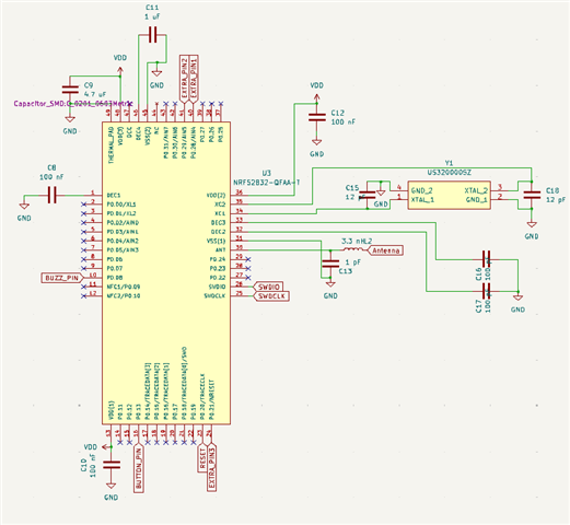
I have some problems with flashing my custom PCB with an nRF52832. I saw online that you can flash the nRF52832 using the nRF52840 DK. I have looked into a lot of the other posts but have not found the answer I am looking for.
I wanted to first test my PCB with a blink example. I set the build configuration to target: nrf52dk/nrf52832.
When I use VSC to flash I get a message saying it uploaded successfully:
[7/7] Linking C executable zephyr\zephyr.elf
Memory region Used Size Region Size %age Used
FLASH: 26356 B 512 KB 5.03%
RAM: 5760 B 64 KB 8.79%
IDT_LIST: 0 GB 32 KB 0.00%
Generating files from C:/Users/kaare/OneDrive/Desktop/Create/nRF_SDK_course/ncs-fund/l2/l2_e1_copy/build_1/l2_e1_copy/zephyr/zephyr.elf for board: nrf52dk
[3/5] cmd.exe /C "cd /D C:\Users\kaare\OneDrive\Desktop\Create\nRF_SDK_course\ncs-fund\l2\l2_e1_copy\build_1\_sysbuild && C:[5/5] Generating ../merged.hex
-- west flash: using runner nrfutil
-- runners.nrfutil: reset after flashing requested
-- runners.nrfutil: Flashing file: C:\Users\kaare\OneDrive\Desktop\Create\nRF_SDK_course\ncs-fund\l2\l2_e1_copy\build_1\merged.hex
-- runners.nrfutil: Erasing address ranges touched by firmware
-- runners.nrfutil: Programming image
-- runners.nrfutil: Verifying image
-- runners.nrfutil: Reset
-- runners.nrfutil: Board(s) with serial number(s) 683013092 flashed successfully.
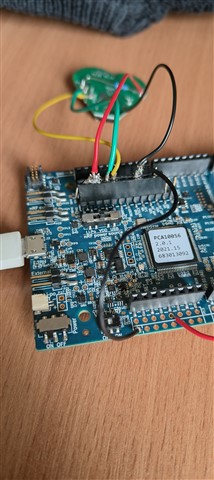
But when I then test with a multimeter on my exposed pins I get no change (just a floating value of around 0.8V)
I have followed the wiring schematics that others have pointed out, but still don't get anything.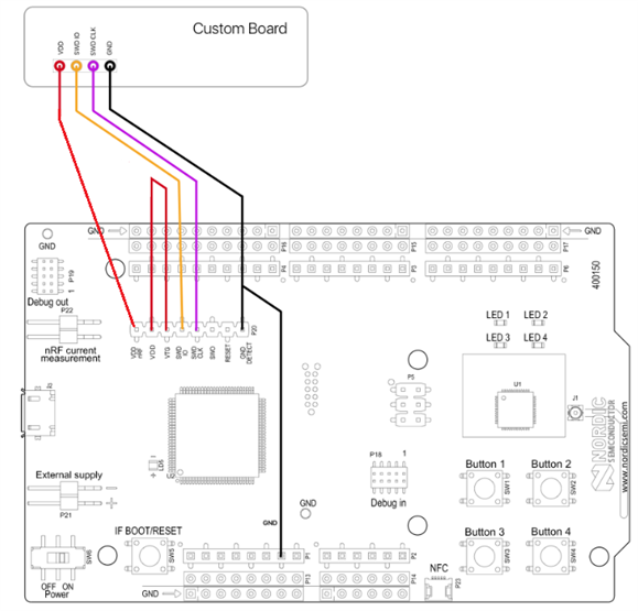
I thought the problem might lie in the SWD pins not being properly connected but I tried resoldering them and that didn't change anything.
I also tried using a USB-C cable which I cut up to expose the relevant wires and connect those but that didn't work either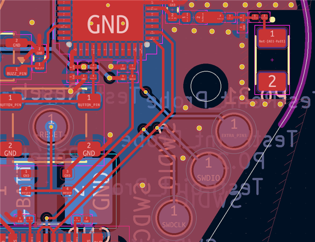
Additionally, I found out that I accidentally connected my reset pin to the wrong label and thus it is connected to the extra pad (uppermost of the three pads on the bottom side) instead of a button. I wired a 10k pull-up resistor to the pad (see pictures below) so it shouldn't cause problems.
I have tried both powering the nRF52832 with the onboard power management circuit (giving 3.3V VDD) and by powering the board using the nRF52840 DK VDD (3V VDD).
I have tested continuity between the test pads and the pins and also between the test pads and the nRF52840 DK and all looks okay.
I have also tried testing the J-LINK RTT viewer to look at LOG messages in the blink example, and for the nRF52840 DK it works fine, but when connected to the nRF52832 (which it can connect to) it does not give any messages.
I hope you can help me and please don't hesitate to ask me for more information if needed.