
Hello,
I am using the ANNA-B112 module with nRF52832 to communicate to an AD5940 AFE using SPI1. I am also communicating with three other sensors using I2C0. This project uses nRF Connect SDK v3.0.0. I have posted the .dts and .overlay files that I am using for this project below.
ubx_evkannab1_nrf52832.dts
/*
* Copyright (c) 2021 u-blox AG
*
* SPDX-License-Identifier: Apache-2.0
*/
/dts-v1/;
#include <nordic/nrf52832_qfaa.dtsi>
#include "ubx_evkannab1_nrf52832-pinctrl.dtsi"
#include <zephyr/dt-bindings/input/input-event-codes.h>
/ {
model = "u-blox EVK-ANNA-B1 NRF52832";
compatible = "u-blox,ubx_evkannab1_nrf52832";
chosen {
zephyr,console = &uart0;
zephyr,shell-uart = &uart0;
zephyr,uart-mcumgr = &uart0;
zephyr,bt-mon-uart = &uart0;
zephyr,bt-c2h-uart = &uart0;
zephyr,sram = &sram0;
zephyr,flash = &flash0;
zephyr,code-partition = &slot0_partition;
};
leds {
compatible = "gpio-leds";
led0: led_0 {
/* ANNA-B1 GPIO_29 */
gpios = <&gpio0 27 GPIO_ACTIVE_LOW>;
label = "Red LED";
};
led1: led_1 {
/* ANNA-B1 GPIO_30 */
gpios = <&gpio0 25 GPIO_ACTIVE_LOW>;
label = "Green LED";
};
led2: led_2 {
/*ANNA-B1 GPIO_31 */
gpios = <&gpio0 26 GPIO_ACTIVE_LOW>;
label = "Blue LED";
};
};
pwmleds {
compatible = "pwm-leds";
red_pwm_led: red_pwm_led {
pwms = <&pwm0 0 PWM_MSEC(20) PWM_POLARITY_INVERTED>;
};
green_pwm_led: green_pwm_led {
pwms = <&pwm0 1 PWM_MSEC(20) PWM_POLARITY_INVERTED>;
};
blue_pwm_led: blue_pwm_led {
pwms = <&pwm0 2 PWM_MSEC(20) PWM_POLARITY_INVERTED>;
};
};
buttons {
compatible = "gpio-keys";
button0: button_0 {
/* EVK-ANNA-B1 SW1 button */
gpios = <&gpio0 25 (GPIO_PULL_UP | GPIO_ACTIVE_LOW)>;
label = "Push button switch SW1";
zephyr,code = <INPUT_KEY_0>;
};
button1: button_1 {
/* EVK-ANNA-B1 SW2 button */
gpios = <&gpio0 24 (GPIO_PULL_UP | GPIO_ACTIVE_LOW)>;
label = "Push button switch SW2";
zephyr,code = <INPUT_KEY_1>;
};
};
arduino_header: connector {
compatible = "arduino-header-r3";
#gpio-cells = <2>;
gpio-map-mask = <0xffffffff 0xffffffc0>;
gpio-map-pass-thru = <0 0x3f>;
gpio-map = <0 0 &gpio0 4 0>, /* A0 */
<1 0 &gpio0 5 0>, /* A1 */
<2 0 &gpio0 28 0>, /* A2 */
<3 0 &gpio0 29 0>, /* A3 */
<4 0 &gpio0 30 0>, /* A4 */
<5 0 &gpio0 31 0>, /* A5 */
<6 0 &gpio0 2 0>, /* D0 */
<7 0 &gpio0 3 0>, /* D1 */
<8 0 &gpio0 19 0>, /* D2 */
<9 0 &gpio0 11 0>, /* D3 */
<10 0 &gpio0 27 0>, /* D4 */
<11 0 &gpio0 26 0>, /* D5 */
<12 0 &gpio0 10 0>, /* D6 */
<13 0 &gpio0 9 0>, /* D7 */
<14 0 &gpio0 14 0>, /* D8 */
<15 0 &gpio0 24 0>, /* D9 */
<16 0 &gpio0 22 0>, /* D10 */
<17 0 &gpio0 23 0>, /* D11 */
<18 0 &gpio0 18 0>, /* D12 */
<19 0 &gpio0 20 0>, /* D13 */
<20 0 &gpio0 15 0>, /* D14 */
<21 0 &gpio0 16 0>; /* D15 */
};
arduino_adc: analog-connector {
compatible = "arduino,uno-adc";
#io-channel-cells = <1>;
io-channel-map = <0 &adc 1>, /* A0 = P0.4 = AIN1 */
<1 &adc 2>, /* A1 = P0.5 = AIN2 */
<2 &adc 4>, /* A2 = P0.28 = AIN4 */
<3 &adc 5>, /* A3 = P0.29 = AIN5 */
<4 &adc 6>, /* A4 = P0.30 = AIN6 */
<5 &adc 7>; /* A5 = P0.31 = AIN7 */
};
/* These aliases are provided for compatibility with samples */
aliases {
led0 = &led0;
led1 = &led1;
led2 = &led2;
pwm-led0 = &red_pwm_led;
pwm-led1 = &green_pwm_led;
pwm-led2 = &blue_pwm_led;
red-pwm-led = &red_pwm_led;
green-pwm-led = &green_pwm_led;
blue-pwm-led = &blue_pwm_led;
sw0 = &button0;
sw1 = &button1;
watchdog0 = &wdt0;
};
};
® {
regulator-initial-mode = <NRF5X_REG_MODE_DCDC>;
};
&adc {
status = "okay";
};
&uicr {
gpio-as-nreset;
};
&gpiote {
status = "okay";
};
&gpio0 {
status = "okay";
};
&uart0 {
compatible = "nordic,nrf-uarte";
status = "okay";
current-speed = <115200>;
pinctrl-0 = <&uart0_default>;
pinctrl-1 = <&uart0_sleep>;
pinctrl-names = "default", "sleep";
};
arduino_i2c: &i2c0 {
compatible = "nordic,nrf-twi";
status = "okay";
pinctrl-0 = <&i2c0_default>;
pinctrl-1 = <&i2c0_sleep>;
pinctrl-names = "default", "sleep";
};
&i2c1 {
compatible = "nordic,nrf-twi";
/* Cannot be used together with spi1. */
/* status = "okay"; */
pinctrl-0 = <&i2c1_default>;
pinctrl-1 = <&i2c1_sleep>;
pinctrl-names = "default", "sleep";
};
&pwm0 {
status = "okay";
pinctrl-0 = <&pwm0_default>;
pinctrl-1 = <&pwm0_sleep>;
pinctrl-names = "default", "sleep";
};
arduino_spi: &spi0 {
compatible = "nordic,nrf-spi";
/* Cannot be use simultaneously with i2c0 */
/* status = "okay"; */
cs-gpios = <&arduino_header 16 GPIO_ACTIVE_LOW>; /* D10 */
pinctrl-0 = <&spi0_default>;
pinctrl-1 = <&spi0_sleep>;
pinctrl-names = "default", "sleep";
};
&spi1 {
compatible = "nordic,nrf-spi";
status = "okay";
pinctrl-0 = <&spi1_default>;
pinctrl-1 = <&spi1_sleep>;
pinctrl-names = "default", "sleep";
};
&flash0 {
partitions {
compatible = "fixed-partitions";
#address-cells = <1>;
#size-cells = <1>;
boot_partition: partition@0 {
label = "mcuboot";
reg = <0x00000000 0xc000>;
};
slot0_partition: partition@c000 {
label = "image-0";
reg = <0x0000C000 0x32000>;
};
slot1_partition: partition@3e000 {
label = "image-1";
reg = <0x0003E000 0x32000>;
};
scratch_partition: partition@70000 {
label = "image-scratch";
reg = <0x00070000 0xa000>;
};
storage_partition: partition@7a000 {
label = "storage";
reg = <0x0007a000 0x00006000>;
};
};
};
ubx_evkannab1_nrf52832.overlay
&i2c1 {status = "disabled";};
&i2s0 {status = "disabled";};
&uart0 {status = "disabled";};
&arduino_i2c {status = "disabled";};
&adc {status = "disabled";};
&pwm0 {status = "disabled";};
arduino_spi: &spi0 {status = "disabled";};


/ {
    gpiocustom {
        compatible = "gpio-keys";

		// BQ25155 LP: nRF Pin 3 -> ANNA-B112 Pin 19
        gpiocustom0: gpiocustom_0 {
            label = "GPIO_BQ25155LP";
            gpios = <&gpio0 3 (GPIO_OPEN_SOURCE)>;
        };

		// AD5940 CS: nRF Pin 2 -> ANNA-B112 Pin 20
		gpiocustom1: gpiocustom_1 {
			label = "GPIO_AD5940CS";
			gpios = <&gpio0 2 (GPIO_PULL_UP | GPIO_ACTIVE_LOW)>;
		};

		// AD5940 RESET: nRF Pin 31 -> ANNA-B112 Pin 25
		gpiocustom2: gpiocustom_2 {
			label = "GPIO_AD5940RESET";
			gpios = <&gpio0 31 (GPIO_PULL_UP | GPIO_ACTIVE_LOW)>;
		};

		// AD5940 INT0: nRF Pin 4 -> ANNA-B112 Pin 24
		gpiocustom3: gpiocustom_3 {
			label = "GPIO_AD5940INT0";
			gpios = <&gpio0 4 (GPIO_PULL_DOWN | GPIO_ACTIVE_LOW)>;
		};
    };

    aliases {
        bq25155lp = &gpiocustom0;
		ad5940cs = &gpiocustom1;
		ad5940reset = &gpiocustom2;
		ad5940int0 = &gpiocustom3;
    };
};

&gpio0 {
	status = "okay";
	sense-edge-mask = < 0xffffffff >;
};

&spi1 {
    compatible = "nordic,nrf-spi";
    status = "okay";
    pinctrl-0 = <&spi1_default>;
    pinctrl-1 = <&spi1_sleep>;
    pinctrl-names = "default", "sleep";

	// AD5940: Potentiostat
    ad5940: ad5940@0 {
        compatible = "vnd,spi-device";
        reg = <0>;
        spi-max-frequency = <1600000>;
        label = "ad5940";
    };
};

&i2c0 {
    status = "okay";
	pinctrl-0 = <&i2c0_default>;
	pinctrl-1 = <&i2c0_sleep>;
	pinctrl-names = "default", "sleep";

	// BQ25155: Battery Management System
    bq25155: bq25155@6B {
		compatible = "i2c-device";
		status = "okay";
		reg = < 0x6B >;
	};

	// HDC2022: Temperature and Humidity Sensor
	hdc20xx: hdc20xx@40 {
		compatible = "i2c-device";
		status = "okay";
		reg = < 0x40 >;
	};

	// BMA400: Accelerometer
	bma400: bma400@14 {
		compatible = "i2c-device";
		status = "okay";
		reg = < 0x14 >;
	};
};

&pinctrl {
	// I2C Pin Definition
	// SCL: nRF Pin 16 -> ANNA-B112 Pin 15
	// SDA: nRF Pin 15 -> ANNA-B112 Pin 14
    /omit-if-no-ref/ i2c0_default: i2c0_default {
		group1  {
			psels = <NRF_PSEL(TWIM_SCL, 0, 16)>,
					<NRF_PSEL(TWIM_SDA, 0, 15)>;
		};
	};

	/omit-if-no-ref/ i2c0_sleep: i2c0_sleep {
		group1  {
			psels = <NRF_PSEL(TWIM_SCL, 0, 16)>,
					<NRF_PSEL(TWIM_SDA, 0, 15)>;
			low-power-enable;
		};
	};

	// SPI Pin Definitions
	// SCK: nRF Pin 20 -> ANNA-B112 Pin 45
	// MOSI: nRF Pin 19 -> ANNA-B112 Pin 35
	// MISO: nRF Pin 24 -> ANNA-B112 Pin 38
	spi1_default: spi1_default {
		group1 {
			psels = <NRF_PSEL(SPIM_SCK, 0, 20)>,
					<NRF_PSEL(SPIM_MOSI, 0, 19)>,
					<NRF_PSEL(SPIM_MISO, 0, 24)>;
		};
	};
	spi1_sleep: spi1_sleep {
		group1 {
			psels = <NRF_PSEL(SPIM_SCK, 0, 20)>,
					<NRF_PSEL(SPIM_MOSI, 0, 19)>,
					<NRF_PSEL(SPIM_MISO, 0, 24)>;
			low-power-enable;
		};
	};
};

/delete-node/ &slot1_partition;
/delete-node/ &scratch_partition;
/delete-node/ &storage_partition;

&flash0 {
	partitions {
		compatible = "fixed-partitions";
		#address-cells = <1>;
		#size-cells = <1>;

		// Boot Partition: 49152 B
		boot_partition: partition@0 {
			label = "mcuboot";
			reg = <0x00000000 0xc000>;
		};
		// Slot0 Partition: 204800 B
		slot0_partition: partition@c000 {
			label = "image-0";
			reg = <0x0000C000 0x32000>;
		};
		// Slot1 Partition: 4096 B
		slot1_partition: partition@3e000 {
			label = "image-1";
			reg = <0x0003E000 0x1000>;
		};
		// Scratch Partition: 4096 B
		scratch_partition: partition@3f000 {
			label = "image-scratch";
			reg = <0x0003F000 0x1000>;
		};
		// Storage Partition (For Encryption Keys): 8192 B
		storage_partition: partition@40000 {
			label = "storage";
			reg = <0x00040000 0x0002000>;
		};
		// File System Partition: 253952 B
		fs_partition: partition@42000 {
			label = "fs";
			reg = <0x42000 0x3e000>;
		};
	};
};
What I am noticing is that initially the idle current of the system will be low as expected around 4-5 uA. However, after a few seconds, the idle current will slowly start to increase and peak at around 500 uA. After some more time the idle current may continue to fluctuate between 4 uA - 500 uA seemingly at random. Functionality of the communication is not affected.
This behavior is observed on both the ANNA-B112 EVK and on a custom PCB board. On the ANNA-B112 EVK, if I touch the button SW2 with my finger (touch the button housing not press the button down) the idle current will very quickly go back down to 4-5 uA as expected and communication functionality is not affected.
(Note ANNA-B112 module IO_38 = nRF52832 P0.24)
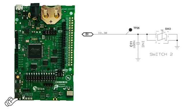
I believe the issue is related to SPI and GPIOs communicating with the AD5940. If you notice, I use nRF52832 pin 24 for MISO and the ANNA-B112 EVK uses the same pin for SW2. I tried deleting the buttons definition on the .dts file, but this did not change the idle current fluctuation behavior.
I am not sure this is an EVK related issue because I am also noticing the same behavior on a custom PCB which has no button. For reference I don't use any external pullup or pulldown resistors on SPI, but I do use a 10K pullup for I2C.
What could cause the idle current to fluctuate like this when using SPI?
Thank you,
Crisvin Kadambathil

