
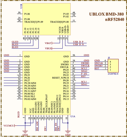
I am trying to program a custom PCB board that has a BMD380 (10059 chip). The BMD380 is setup in HV mode and is powered by a Li-Ion battery (please see the schematic below).
The DK board is NRF52840-DK v3.0.2.
Until now we have no way to tell why the external board is not picked by the SWD. Here is what we did:
Case 1: Powering External Board with Li-Ion:
NRF DK Board (P20) -> External BMD380 PCB
SWD I/O (P20) ---> SWDI/O
SWD CLK P(20) --> SWDCLK
GND (P1) --> GND
RESET (P20) --> RESET
SWD_SET ----> VCCMCU (1.8V)
P.S: I don't see a GND_DETECT pin (there is no label on the pin below RESET pin on P20 in v3.0.2) but to be sure, I connected that pin to GND with the external board.
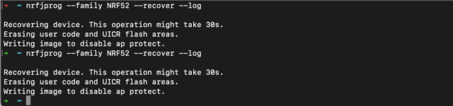
No external board is detected on NRF Connect App for Desktop (Programmer) as well as on nrfjprog (cmd: nrfjprog --famy NRF52 --recover --log). NRFJProg programs the on DK NRF. Please see image below for NRFJprog output:
Case 2: Power External Board with NRF52840 DK board
After not able to get the external board on SWD and searching this forum for the answers, I stumbled upon the correct documentation of the v3.0.2 which states that If SB47 is connected, then VDD_nRF on P20 can power the external board and SWD won't see the on-DK NRF chip. This is not true really. When I soldered the SB47, I can still see NRF (even before I connect anything from external board PCB).
Ignoring the above ambiguity (and out for glory), I powered the external PCB with VDD_nRF as follow:
NRF DK Board (P20) -> External BMD380 PCB
SWD I/O (P20) ---> SWDI/O
SWD CLK (P20) --> SWDCLK
GND (P1) --> GND
RESET (P20) --> RESET
VBAT ----> VDD_nRF (P20)
SWD_SET (P20) ----> VDD_nRF (P20, on DK board)
NOT LABELLED PIN after RESET on P20 ---> GND (P1)
Soldered SCB47 (just below the DEBUG_OUT connector physically).
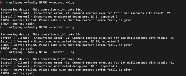
Unfortunately in this case the DK board still sees internal NRF chip but sometimes the NRFJProg output has changed (see below):
Can anyone please help me understand what I might be doing wrong?
My goal is to upload a boot loader with serial and BLE DFU enabled, and DFU triggers enabled and then not use SWD again.
P.S: If necessary, I do have a bunch of NRF52840 USB dongle that I can use to check if SWD on DK is working, please let me know if it's worth trying that?
thank you, much appreciated.

