nrf5340 GPIO drive strength wonky

Dear All:

I have a very strange issue that has me scratching my head. I am programming a GPIO to provide hardware reset to an i2c GPIO expanver (pcal6408a). The io expander is fully supported in zephyr 4.3.0 mainline (I am using the zephyr 4.3.0 release branch). I have described the pin in the device tree and it compiles cleanly. when I run the init sequence for the io expander the code correctly sets the gpio to S0S1 drive strength, and then pulses the gpio low for 1uS with no returned error codes. Unfortunately when I look at it on the oscilloscope the gpio never goes low.

All of this happens during the initialization that runs before control reaches main(). I looked at the init priorities and everything is happening in the correct order.

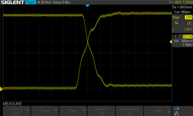
Eventually I wrote a loop in main() that simply toggles the gpio P1.04 alternating high and low once per millisecond. When I look at the signal on the oscilloscope it the rise and fall times are good (about 15ns). If I force the drive strength to H0H1 the rise and fall times are about 7ns. This says to me that the hardware is all good, both inside the chip, and on my external wiring. From the rise and fall times, and the  rise and fall times published in the datasheet, I can estimate that the capacitance on the line is about 22pF, which seems about right.

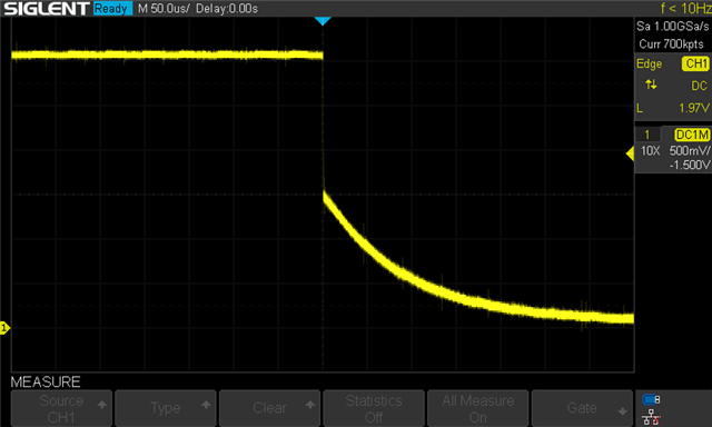
Now here is where it gets weird. if I put a break point i the middle of the loop, the rising edge looks great, but the falling edge is very bad. the signal falls the from 3.3V to 1.7V at the normal rate, then the pin goes tristate. It then slowly falls to zero over about 200uS, this is exactly the time you would expect with 22pF and a 10MOhm pull-down, the scope probe is a 10MOhms resistance to ground..

When the processor comes out of reset and attempts to send the reset pulse to the pcal6408a it drives down to 1.7V, then goes tri-state, this is why the pcal6408a never properly resets, and also why I could never catch the reset pulse on the oscilloscope.

At this point I haven't tried a different board, or a different gpio, that is my next thing to try (possibly tomorrow). I did read all of the errata for the nrf5340 and didn't see anything about this issue.

I have two suspicions:

1) somehow the gpiote is programmed to put the pin in tristate if it goes low. I single stepped through the gpiote code that gets run when the pin is configured and the code appears to be turning the gpiote off for this pin.

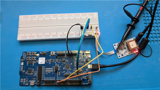
2) I have a strange setup for the core power. I am using a uBlox NORA module which contains the nrf5340 (date code week 24 of 2025, or week 25 of 2024). I am powering the module from an external 3.3V supply. uBlox documentation doesn't .specify any particular settings I need to put in the UICR. I am using the same settings as the nrf5340dk. Is it possible that I have the UICR programmed incorrectly and this is why the pin goes tri-state on falling edges?

I am looking for some hints of things I could do next to try to find the root cause of the issue.

Thanks in advance for your help.

  • Today I moved everything to the nrf5340dy (rev 2.0.2), and build a simplified app to demonstrate the problem. It is 100% repeatable on the nrf5340dk with gpio P1.04. 

    First an oscilloscope plot of the loop running with no break points. time base is 20nS/division

    Then a scope shot of the falling edge when it fails (the first time as the pcal6408 is initializing, or when there is a break-point in the main loop at the sleep call. Note the change in timebase to 50uS/div.

    The test program only needs an overlay to describe the pins and connections. Here is my test setup: The white boards are my design. The small one on the breadboard is a breakout to the flex circuit, and the board near the 'scope probe is a sensor board. 

    app.overlay

    /{
            aliases {
                    nreset = &nreset;
    	};
            leds {
                    status = "okay";
                    compatible = "gpio-leds";
                    nreset: nreset {
                            gpios = <&gpio1 8 GPIO_ACTIVE_LOW>;
                            label = "nRESET";
                    };
    	};
    };
    
    &pinctrl {
            i2c1_default: i2c1_default {
                    group1 {
                            psels = <NRF_PSEL(TWIM_SDA, 1, 2)>,
                                    <NRF_PSEL(TWIM_SCL, 1, 3)>;
                    };
            };
    
            i2c1_sleep: i2c1_sleep {
                    group1 {
                            psels = <NRF_PSEL(TWIM_SDA, 1, 2)>,
                                    <NRF_PSEL(TWIM_SCL, 1, 3)>;
                            low-power-enable;
                    };
            };
    };
    
    &i2c1 {
            status = "okay";
            compatible = "nordic,nrf-twim";
            status = "okay";
            pinctrl-0 = <&i2c1_default>;
            pinctrl-1 = <&i2c1_sleep>;
            pinctrl-names = "default", "sleep";
            zephyr,concat-buf-size = <512>;
    
            gpio_expander1_bank1: pcal6408a@20 {
                    compatible = "nxp,pcal6408a";
                    reg = <0x20>;
                    gpio-controller;
                    #gpio-cells = <2>;
                    ngpios = <8>;
                    int-gpios = <&gpio1 4 GPIO_ACTIVE_LOW>;
                    reset-gpios = <&gpio1 8 GPIO_ACTIVE_LOW>;
            };
    };
    

    main.c

    /*
     * Copyright (c) 2012-2014 Wind River Systems, Inc.
     *
     * SPDX-License-Identifier: Apache-2.0
     */
    
    #include <stdio.h>
    #include <zephyr/kernel.h>
    #include <zephyr/device.h>
    #include <zephyr/drivers/gpio.h>
    #include <zephyr/dt-bindings/gpio/nordic-nrf-gpio.h>
    //#include <zephyr/drivers/sensor.h>
    
    #define NRESET_NODE     DT_ALIAS(nreset)
    
    
    int main(void)
    {
    int ret;
    const struct gpio_dt_spec nreset = GPIO_DT_SPEC_GET(NRESET_NODE,gpios);
    
    	printf("Hello World! %s\n", CONFIG_BOARD_TARGET);
    
            /* pulse nreset to prove it works */
            ret = gpio_is_ready_dt(&nreset);
            if (ret != true) {
                    printk("Error %d: relay is not ready on %s pin %d\n",
                                    ret, nreset.port->name, nreset.pin);
            }
    
            ret = gpio_pin_configure_dt(&nreset, GPIO_OUTPUT_ACTIVE|NRF_GPIO_DRIVE_S0S1);
            if (ret < 0) {
                    printk("Error %d: output active %s pin %d\n",
                                    ret, nreset.port->name, nreset.pin);
            }
            k_msleep(10);
            for( int i=1; i<100000; i++) {
                    ret = gpio_pin_set_dt(&nreset, !(i&1));
                    if (ret < 0) {
                            printk("Error %d: relay is not output inactive %s pin %d\n",
                                            ret, nreset.port->name, nreset.pin);
                    }
                    k_msleep(1);
                    // measured fall time is 20nS standard drive,
                    // 10nS high drive (H0S1), and 200uS with pulldown
            }
            printf("nreset test done\n");
    
    	return 0;
    }
    

  • Hello,

    Can you try a pull down resistor on the input GPIO pin (P1.04)?

    Also I guess you are using internal pull up resistor on the I2C pin. So, in the device tree you have to add bias  ''bias-pull-up'' line in overlay file of I2c.

  • I have external pull-ups on the i2c lines, so they don't really need the internal pullups.

    I am away on vacation for 12 days, I'll give adding a pull-down a try when I get back.

  • I finally got to the bottom of this. I had an error on my schematic, which inadvertently attached P1.04 to a power domain that was not powered up correctly. The slow fall was due to the current limit on P1.04 limiting the rate of discharge on the capacitors on the power domain.

    Thanks for your time, and giving me a hint that sent me looking in the right direction.

  • I am glad that you have solved the issue. Thanks for letting me know. 

Related