
Hello,
I designed a new custom PCB with nRF52832 and I would like to ask you for verification.
I have the MCU and some components regarding Battery Management.
The idea is that since the device will not be used all the time, I want the switch to completely turn it off, and disconnect it from the battery.
So, I made the circuit with the following logic: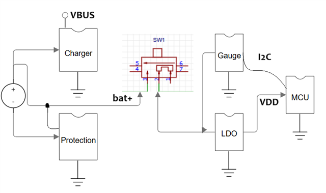
Description:
- The system is powered by a LiPo Battery.
- The Battery connects to a Battery Protection IC, a Battery Charger IC, an LDO and a Gauge IC.
- The switch "divides" the system in two parts. Part A is Battery with Charger and Protection. Part B is LDO, Gauge, nRF52832 and the rest components that are supplied by the VDD rail.
The idea is that when the switch is off, the battery is still connected to the protection and to the Charger. Thus the battery can be charged with protection even if the rest of the system is off.
My question is the whole circuit correct?
Will there be any problem when the switch is off because of the fact that the MCU and all of the components have the same ground?
Or the best way to turn it completely off is by putting the switch like this: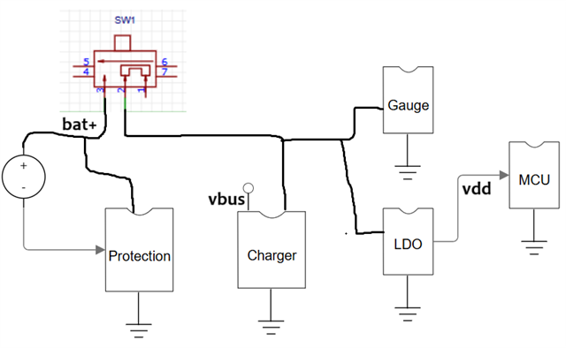
meaning that moving also the charger by the Part B side. and when the switch is turned off will cut generally the supply apart from the protection. However this way the battery will not charge if the switch is off (forgotten off by the user).
Thank you very much in advance.
