nrf9151dk GPS antenna 50-ohm impedance coplanar transmission line

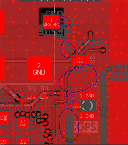
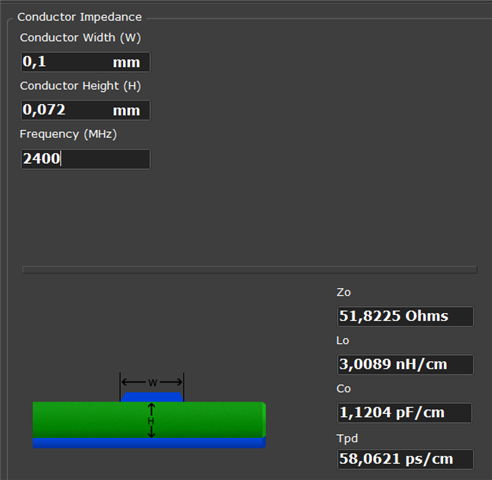
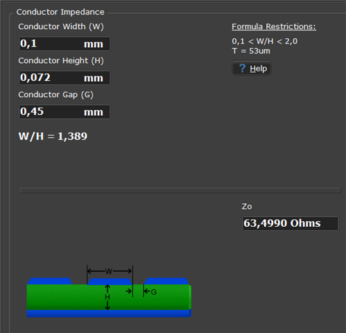
On the nRF9151dk, the transmission line coming from the nRF9151 starts with a 0.1 mm trace width and a 0.46 mm gap, which corresponds to a 50 Ω characteristic impedance. However, before reaching the antenna, the trace width increases to 0.2 mm and the gap decreases to 0.126 mm. This no longer appears to be a 50 Ω line. Why is that?

Parents
  • Hello Tasos,
    this is a good observation. There's been some discussion here about this and the distance between trace and ground is grey area/border line coplanar wave guide and not a microstrip trace.  
    See the screen shots below. If you consider the wider distances to be wide enough for it to be a microstrip, you have a 50Ohm-ish trace. If you consider it to be a coplanar wave guide, it ends up having a different impedance. I don't think either will be spot on in the case of the DK and you end up somewhere in between. So please make sure you implement a 50Ohm transmission line for you use.
    So the short story is slightly different views here on when a coplanar waveguide becomes a microstrip and vice versa. 
    Best regards
    Asbjørn
Reply
  • Hello Tasos,
    this is a good observation. There's been some discussion here about this and the distance between trace and ground is grey area/border line coplanar wave guide and not a microstrip trace.  
    See the screen shots below. If you consider the wider distances to be wide enough for it to be a microstrip, you have a 50Ohm-ish trace. If you consider it to be a coplanar wave guide, it ends up having a different impedance. I don't think either will be spot on in the case of the DK and you end up somewhere in between. So please make sure you implement a 50Ohm transmission line for you use.
    So the short story is slightly different views here on when a coplanar waveguide becomes a microstrip and vice versa. 
    Best regards
    Asbjørn
Children
No Data
Related