Hi,
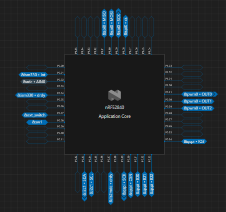
I have a custom PCB that I am programming. The PCB uses a NRF52840-QFAA chip. I want to save a file inside of the external flash chip (W25Q256JVEIQ). It is connected using QSPI. I have created the device tree, the prj.conf, the pm_static.yml, and the main.c files. However, every time I run the code I get this error.
I was able to configure the external flash using partition manager but cant seem to read or write files inside the flash.
I have attached my files below. Can anyone help me with this? Even after resetting the chip it fails to mount.
Do I have to erase the external flash completely? How do I solve this? 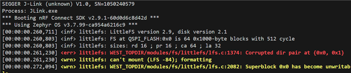
#include <zephyr/kernel.h>
#include <zephyr/fs/fs.h>
#include <zephyr/fs/littlefs.h>
#include <zephyr/storage/flash_map.h>
#include <zephyr/logging/log.h>
#include <string.h>

LOG_MODULE_REGISTER(app, LOG_LEVEL_INF);

FS_LITTLEFS_DECLARE_DEFAULT_CONFIG(lfs_cfg);

static struct fs_mount_t lfs_mnt = {
    .type = FS_LITTLEFS,
    .fs_data = &lfs_cfg,
    .storage_dev = (void *)FIXED_PARTITION_ID(littlefs_storage),
    .mnt_point = "/lfs",
};

static int write_board_id(uint32_t id)
{
    struct fs_file_t file;
    fs_file_t_init(&file);

    int rc = fs_open(&file, "/lfs/id.txt",
                     FS_O_CREATE | FS_O_WRITE | FS_O_TRUNC);
    if (rc < 0) {
        LOG_ERR("fs_open failed: %d", rc);
        return rc;
    }

    char buf[16];
    int len = snprintk(buf, sizeof(buf), "%u\n", id);

    rc = fs_write(&file, buf, len);
    if (rc < 0) {
        LOG_ERR("fs_write failed: %d", rc);
    }

    fs_close(&file);
    return rc;
}

void main(void)
{
    int rc;

    /* First mount attempt */
    rc = fs_mount(&lfs_mnt);
    if (rc < 0) {
        LOG_WRN("Mount failed (%d), formatting...", rc);

    rc = fs_mkfs(FS_LITTLEFS,
        FIXED_PARTITION_ID(littlefs_storage),
        &lfs_cfg,
        0);
        if (rc < 0) {
            LOG_ERR("fs_mkfs failed: %d", rc);
            return;
        }

        rc = fs_mount(&lfs_mnt);
        if (rc < 0) {
            LOG_ERR("Mount after format failed: %d", rc);
            return;
        }
    }

    LOG_INF("LittleFS mounted");

    /* Set board ID here (1–10) */
    uint32_t board_id = 3;

    rc = write_board_id(board_id);
    if (rc == 0) {
        LOG_INF("Board ID written successfully");
    }
}
# RTT console
CONFIG_USE_SEGGER_RTT=y
CONFIG_RTT_CONSOLE=y

# Logging
CONFIG_LOG=y
CONFIG_LOG_MODE_DEFERRED=y
CONFIG_LOG_BACKEND_RTT=y

# Flash + map
CONFIG_FLASH=y
CONFIG_FLASH_MAP=y
CONFIG_FLASH_PAGE_LAYOUT=y
CONFIG_FLASH_JESD216_API=y

# QSPI NOR
CONFIG_NORDIC_QSPI_NOR=y

# File system
CONFIG_FILE_SYSTEM=y
CONFIG_FILE_SYSTEM_LITTLEFS=y
CONFIG_FILE_SYSTEM_MKFS=y
CONFIG_FS_LITTLEFS_FMP_DEV=y

# Memory
CONFIG_MAIN_STACK_SIZE=4096
CONFIG_SYSTEM_WORKQUEUE_STACK_SIZE=4096
CONFIG_HEAP_MEM_POOL_SIZE=16384
external_flash:
  address: 0x0
  size: 0x02000000   # 32MB
  region: external_flash
  device: ext_flash  # <-- must match DT node label

littlefs_storage:
  address: 0x00000000
  size: 0x00040000   # 256KB
  region: external_flash
  device: ext_flash
/dts-v1/;
#include <nordic/nrf52840_qfaa.dtsi>
// #include "gait_board_NRF52840-pinctrl.dtsi"

/ {
	model = "ProFormIQ, NRF52840-QFAA";
	compatible = "NordicSemiConductor,gait-board-NRF52840";

	chosen {
		zephyr,sram = &sram0;
		zephyr,flash = &flash0;
		zephyr,code-partition = &slot0_partition;
		nordic,pm-ext-flash = &ext_flash;
	};

	// leds {
	// 	compatible = "gpio-leds";
	// 	led_g {
	// 		label = "led_g";
	// 		gpios = <&gpio0 30 GPIO_ACTIVE_HIGH>;
	// 	};

	// 	led_b {
	// 		label = "led_b";
	// 		gpios = <&gpio0 29 GPIO_ACTIVE_HIGH>;
	// 	};

	// 	led_r {
	// 		label = "led_r";
	// 		gpios = <&gpio0 31 GPIO_ACTIVE_HIGH>;
	// 	};
	// };

	pwmleds {
		compatible = "pwm-leds";

		led_r: led_r {
			pwms = <&pwm0 0 PWM_HZ(1000) PWM_POLARITY_INVERTED>;
		};

		led_g: led_g {
			pwms = <&pwm0 1 PWM_HZ(1000) PWM_POLARITY_INVERTED>;
		};

		led_b: led_b {
			pwms = <&pwm0 2 PWM_HZ(1000) PWM_POLARITY_INVERTED>;
		};
	};


	buttons {
		compatible = "gpio-keys";

		sw1: sw1 {
		label = "sw1";
		gpios = <&gpio0 8 (GPIO_PULL_UP | GPIO_ACTIVE_LOW)>;
	};
		ext_switch:ext_switch {
		label = "ext_switch";
		gpios = <&gpio0 7 (GPIO_PULL_UP | GPIO_ACTIVE_LOW)>;
	};

	};
};

/* =========================
 * Internal Flash Partitions
 * ========================= */

&flash0 {
	partitions {
		compatible = "fixed-partitions";
		#address-cells = <1>;
		#size-cells = <1>;

		boot_partition: partition@0 {
			label = "mcuboot";
			reg = <0x00000000 DT_SIZE_K(48)>;
		};

		slot0_partition: partition@c000 {
			label = "image-0";
			reg = <0x0000c000 DT_SIZE_K(472)>;
		};

		slot1_partition: partition@82000 {
			label = "image-1";
			reg = <0x00082000 DT_SIZE_K(472)>;
		};

		storage_partition: partition@f8000 {
			label = "storage";
			reg = <0x000f8000 DT_SIZE_K(32)>;
		};
	};
};


&gpiote {
	status = "okay";
};

&gpio0 {
	status = "okay";
};

&gpio1 {
	status = "okay";
};

&spi0 {
	status = "okay";
	cs-gpios = <&gpio1 8 GPIO_ACTIVE_LOW>;
	pinctrl-0 = <&spi0_default>;
	pinctrl-1 = <&spi0_sleep>;
	pinctrl-names = "default", "sleep";

ism330: ism330dhcx@0 {
		compatible = "st,ism330dhcx";
		reg = <0>; /* CS0 */
		spi-max-frequency = <10000000>;

		/* Data-ready interrupt */
		drdy-gpios = <&gpio0 4 GPIO_ACTIVE_HIGH>;
		int-pin = <1>; /* DRDY routed to INT1 */

		/* Optional but recommended defaults */
		accel-odr = <4>;
		accel-range = <4>;
		gyro-odr = <4>;
		gyro-range = <500>;
	};
};

&pinctrl {
	spi0_default: spi0_default {
		group1 {
			psels = <NRF_PSEL(SPIM_SCK, 1, 9)>,
					<NRF_PSEL(SPIM_MOSI, 1, 10)>,
					<NRF_PSEL(SPIM_MISO, 1, 11)>;
		};
	};

	spi0_sleep: spi0_sleep {
		group1 {
			psels = <NRF_PSEL(SPIM_SCK, 1, 9)>;
		};
	};

	i2c1_default: i2c1_default {
		group1 {
			psels = <NRF_PSEL(TWIM_SDA, 0, 13)>, <NRF_PSEL(TWIM_SCL, 0, 14)>;
		};
	};

	i2c1_sleep: i2c1_sleep {
		group1 {
			psels = <NRF_PSEL(TWIM_SDA, 0, 13)>;
		};
	};

	qspi_default: qspi_default {
		group1 {
			psels = <NRF_PSEL(QSPI_SCK, 0, 19)>,
					<NRF_PSEL(QSPI_CSN, 0, 20)>,
					<NRF_PSEL(QSPI_IO0, 0, 21)>,
					<NRF_PSEL(QSPI_IO1, 0, 22)>,
					<NRF_PSEL(QSPI_IO2, 0, 23)>,
					<NRF_PSEL(QSPI_IO3, 0, 24)>;
		};
	};

	qspi_sleep: qspi_sleep {
		group1 {
			psels = <NRF_PSEL(QSPI_SCK, 0, 19)>;
		};
	};


	pwm0_default: pwm0_default {
			group1 {
				psels = <NRF_PSEL(PWM_OUT0, 0, 31)>,
						<NRF_PSEL(PWM_OUT1, 0, 30)>,
						<NRF_PSEL(PWM_OUT2, 0, 29)>;
			};
		};

		pwm0_sleep: pwm0_sleep {
			group1 {
				psels = <NRF_PSEL(PWM_OUT0, 0, 31)>;
			};
		};

};

&adc {
	status = "okay";
	battery_voltage: battery_voltage {
		compatible = "voltage-divider";
		io-channels = <&adc 0>;   /* AIN0 */
		label = "BATTERY_VOLTAGE";

		/* Replace with your actual resistor values */
		output-ohms = <100>;    /* Rbottom */
		full-ohms = <570>;     /* Rtop + Rbottom */
	};

};

&i2c1 {
	status = "okay";
	pinctrl-0 = <&i2c1_default>;
	pinctrl-1 = <&i2c1_sleep>;
	pinctrl-names = "default", "sleep";

		/* ISS2MDCTR – Magnetometer (open-drain INT) */
	iis2mdc: iis2mdc@1e {
		compatible = "st,iss2mdc";
		reg = <0x1e>;
		/* DRDY is open-drain, active-low */
		drdy-gpios = <&gpio0 17 (GPIO_PULL_UP | GPIO_ACTIVE_LOW)>;
	};

};

&pwm0 {
    status = "okay";
    pinctrl-0 = <&pwm0_default>;
    pinctrl-1 = <&pwm0_sleep>;
    pinctrl-names = "default", "sleep";
};

&qspi {
	status = "okay";
	pinctrl-0 = <&qspi_default>;
	pinctrl-1 = <&qspi_sleep>;
	pinctrl-names = "default", "sleep";

	    ext_flash: flash@0 {
        compatible = "nordic,qspi-nor";
        reg = <0>;
	    size = <0x02000000>; /* 32MB */
        /* Winbond W25Q256JVEIQ */
        sck-frequency = <8000000>;
		readoc = "fastread";
		writeoc = "pp";
	    jedec-id = [ EF 40 19 ];
                /* THIS is the correct QE configuration */
        quad-enable-requirements = "S2B1v1";
		address-size-32;
        label = "QSPI_FLASH";
    };

};