54L frequency calibration issue

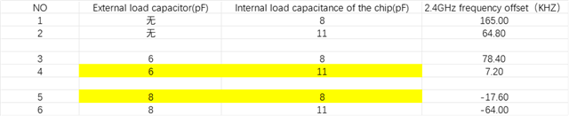
According to the working principle of a crystal oscillator, the load capacitance is inversely proportional to the resonant frequency of the crystal, that is, the larger the load capacitance, the lower the frequency. Why does the combination of an internal 6pF with an external 11pF result in a higher frequency than an internal 8pF with an external 8pF?

For detailed data, refer to the image below.

Parents
  • Hi,

    Your understanding of crystal behavior is correct: a higher effective load capacitance pulls the frequency lower, and a lower load capacitance pulls it higher. The important point is how the effective load capacitance is formed.

    As shown in the Nordic oscillator schematics (LFXO/HFXO) and the load-capacitance equations in the documentation, the crystal sees two capacitances to ground, one on each crystal pin (XL1/XC1 and XL2/XC2). The total load capacitance seen by the crystal across its terminals, including internal and/ external capacitors, PCB stray capacitance, and pin capacitance is therefore the series-equivalent of these two “to-ground” branches. And in the series-equivalent load, the capacitances do not add arithmetically, by general capacitor network theory we can say that actually the smaller branch has a dominant influence on the effective load capacitance.

    Because of this series relationship, different distributions of capacitance can result in different effective CL even if the nominal pF values look similar. For example, a 6 pF / 11 pF split can result in a lower effective load capacitance than an 8 pF / 8 pF split, which explains why the 6 pF / 11 pF split can produce a higher frequency. This behavior is consistent with crystal oscillator theory and Nordic’s documented model.

    Best Regards,
    Syed Maysum

Reply
  • Hi,

    Your understanding of crystal behavior is correct: a higher effective load capacitance pulls the frequency lower, and a lower load capacitance pulls it higher. The important point is how the effective load capacitance is formed.

    As shown in the Nordic oscillator schematics (LFXO/HFXO) and the load-capacitance equations in the documentation, the crystal sees two capacitances to ground, one on each crystal pin (XL1/XC1 and XL2/XC2). The total load capacitance seen by the crystal across its terminals, including internal and/ external capacitors, PCB stray capacitance, and pin capacitance is therefore the series-equivalent of these two “to-ground” branches. And in the series-equivalent load, the capacitances do not add arithmetically, by general capacitor network theory we can say that actually the smaller branch has a dominant influence on the effective load capacitance.

    Because of this series relationship, different distributions of capacitance can result in different effective CL even if the nominal pF values look similar. For example, a 6 pF / 11 pF split can result in a lower effective load capacitance than an 8 pF / 8 pF split, which explains why the 6 pF / 11 pF split can produce a higher frequency. This behavior is consistent with crystal oscillator theory and Nordic’s documented model.

    Best Regards,
    Syed Maysum

Children
  • I don't understand your explanation. Let me elaborate on my test scenario.

    Note that one is the internal load capacitance, and the other is the external load capacitance.

    Assume C_pcb = C_pin = 1 pF.

    Combination A (Internal 6pF + External 11pF):

    C1' = C2' = C_INT + C_EXT + C_pcb + C_pin = 6 + 11 + 1 + 1 = 19 pF

    C_L = (C1' × C2') / (C1' + C2') = 9.5 pF

    Combination B (Internal 8pF + External 8pF):

    C1' = C2' = C_INT + C_EXT + C_pcb + C_pin = 8 + 8 + 1 + 1 = 18 pF

    C_L = (C1' × C2') / (C1' + C2') = 9 pF

    Why is the frequency of Combination A greater than that of Combination B?

  • Hi,

    Thanks for the detailed analysis. Actually the important point here is that Nordic only defines load capacitance equations for either internal or external load capacitors, not for a mixed configuration. When internal and external capacitors are used together, the effective load capacitance cannot be determined precisely from nominal pF values.

    In your case, even simplified estimates show that the difference in effective load capacitance between the two combinations is very small. At this level, non ideal effects such as capacitor tolerance, PCB parasitics, and internal capacitor trim quantization dominate, and the usual trend is no longer guaranteed to determine the measured result. So for predictable frequency behavior, we recommend using either the internal load capacitors or external load capacitors, and tuning based on measured frequency.

    Best Regards,
    Syed Maysum

Related