I am using the nRF52840DK with nRFConnect for VS Code. In Lesson 6 Exercise 1, I connected the DK to a BME280 board I purchased online. The board exposes the four pins needed for I2C comms and I connected them to the DK pins as directed in the exercise. I also use this BME board with a nRF52840 Feather board from Adafruit - and I know it's address is 0x76. I altered the device overlay as shown below to account for this address change.
&i2c21 {
status = "okay";
pinctrl-0 = <&i2c21_default>;
pinctrl-1 = <&i2c21_sleep>;
pinctrl-names = "default", "sleep";
mysensor: mysensor@76{
compatible = "i2c-device";
status = "okay";
reg = < 0x76 >;
};
};
&pinctrl {
/omit-if-no-ref/ i2c21_default: i2c21_default {
group1 {
psels = <NRF_PSEL(TWIM_SCL, 1, 11)>,
<NRF_PSEL(TWIM_SDA, 1, 12)>;
};
};
/omit-if-no-ref/ i2c21_sleep: i2c21_sleep {
group1 {
psels = <NRF_PSEL(TWIM_SCL, 1, 11)>,
<NRF_PSEL(TWIM_SDA, 1, 12)>;
};
};
};
The software builds and flashes, but the output I get when I run the program is : Failed to read register d0, which means the first call to i2c_write_read_dt failed.
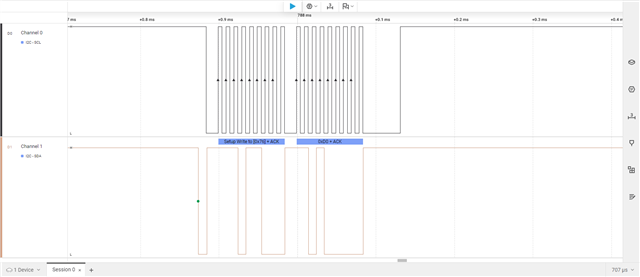
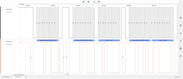
When I probed deeper, I found that the error returned was -5 - which I believe is a general read/write failure. When I connected my logic analyzer (screenshots below) I found that the DK wrote 0x76 ACK and 0xD0 ACK as expected, but the BME never replied. When I probed the Feather board I noticed that the sequence written by the Feather was 0x76 ACK, 0x76 ACK, 0xD0, and the same BME board replied with the expected 0x60. Has anyone seen this, or do you have any hints to fix it?
Thanks Lonnie