Hi,
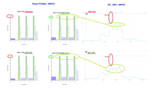
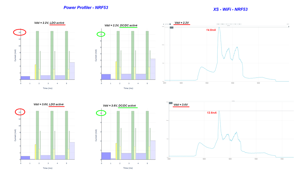
We are facing a strange behavior where the consumption we measure on the nRF5340 doesn't change according to supply voltage like it is supposed to do in DCDC mode.
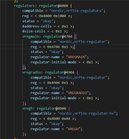
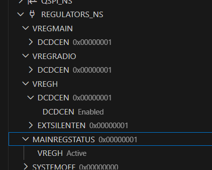
This behavior seems to indicate the nRF5340 is running in LDO mode, but the registers shows that we are supposed to be in DCDC mode :
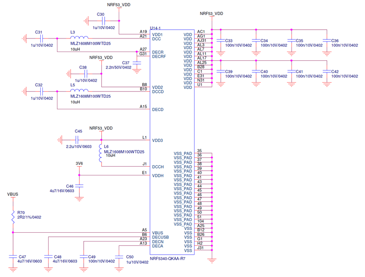
Our wiring diagram is the following (same as product specification v1.6, chapter 9.3.1 Circuit configuration no. 1 for QKAA aQFN94) :
We need help to understand this behavior.
Thank you very much
Best regards