Hello DevZone,
I have wrote a standard Zephyr display driver for one customer, I used sQSPI and Zephyr MSPI API.
I finished the development, but the QSPI (1-1-4 mode) plot on 54LM20 is different from that on 54L15. The code is same.
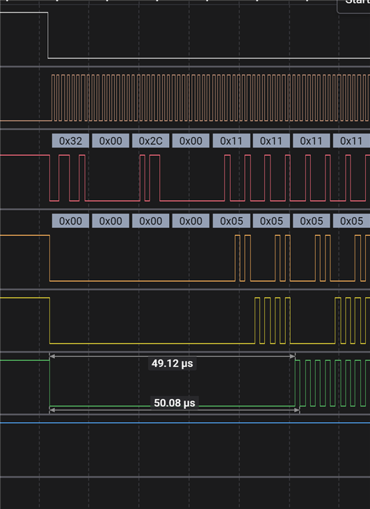
display requirement: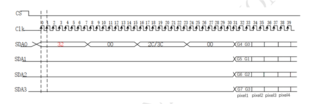
nrf54L15 v1.0.0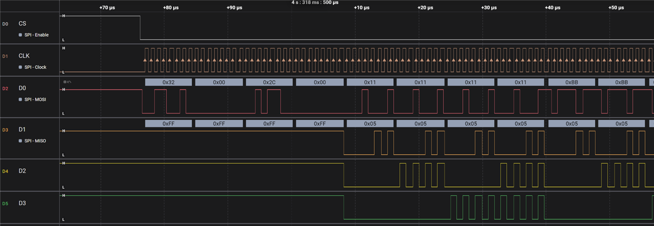
nrf54lm20 v0.3.4: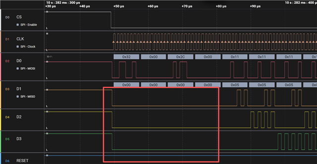
You can see that when transmitting the cmd and address, the voltage of D1, D2, D3 is different.
I'm not sure which one is correct.
Here is my code: github.com/.../display_a6ng.c
My NCS version is v3.2.2
Best regards,
Jayant