Chip Startup Sequence

Hello, I would like to inquire about some technical details regarding the internal module power supply ranges, power-up sequences, and reset voltages for the nRF54L05, nRF54L15, nRF52805, and nRF52820:

  1. The startup sequence during a power ramp-up (increasing voltage).

  2. The voltage threshold that triggers a reset during a power ramp-down (decreasing voltage).

  3. The time from when the core starts until Flash operations or access is available during the startup phase.

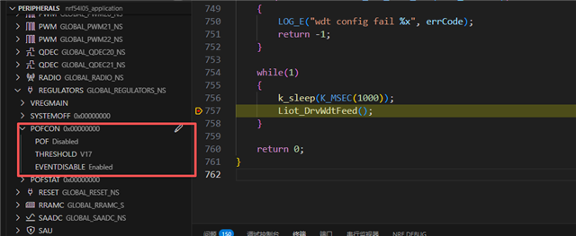
  4. If the Power-Fail Comparator (POF) is configured, the time from when the core starts until the POF becomes effective during the startup phase.

It has been confirmed that there is no relevant information available on the one we inquired about. If the above-mentioned chips differ under these circumstances, please explain them separately.

Parents Reply
  • Hi,
    I encountered some issues enabling POFCON in NCS. Although I added the following configuration in the dts and it appears to be effective in output/zephyr.dts, during debugging I observed that the register did not take effect. Are there any required .config settings or other considerations I need to be aware of?

    regulators: regulator@120000 {
    	compatible = "nordic,nrf54l-regulators";
    	reg = < 0x120000 0x1000 >;
    	status = "okay";
    	#address-cells = < 0x1 >;
    	#size-cells = < 0x1 >;
    	vregmain: regulator@120600 {
    		compatible = "nordic,nrf5x-regulator";
    		reg = < 0x120600 0x1 >;
    		status = "okay";
    		regulator-name = "VREGMAIN";
    		regulator-initial-mode = < 0x1 >;
    	};
    	pofcon: pofcon@120530 {
    		compatible = "nordic,nrf-pofcon";
    		reg = < 0x120530 0x5 >;
    		status = "okay";
    		pofcon-name = "POFCON";
    	};
    };
    

    debug record:

    Kind regards,

    Jing

Children
Related