Hello,
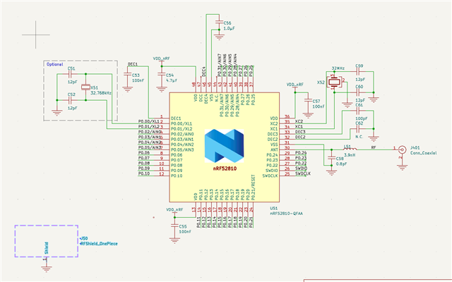
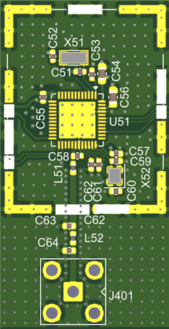
I am currently implementing a Central device using the nRF52810 as part of a Gateway board.
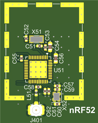
I intend to connect the antenna via a U.FL connector. My current design strictly follows Nordic’s reference design. Additionally, I have incorporated a GND shield pattern to allow for the installation of a Shield CAN in the future.
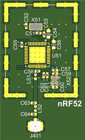
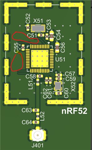
I would like to place the crystal (X51) inside the Shield CAN as well; however, the RF line in the reference design is quite short. Since I am using a 2-layer PCB and the RF line width/spacing follows the reference design, I am concerned about extending it.
If I need to lengthen the RF line, what is the best approach? Should I implement an additional pi-network for matching, or are there other layout considerations I should follow?