
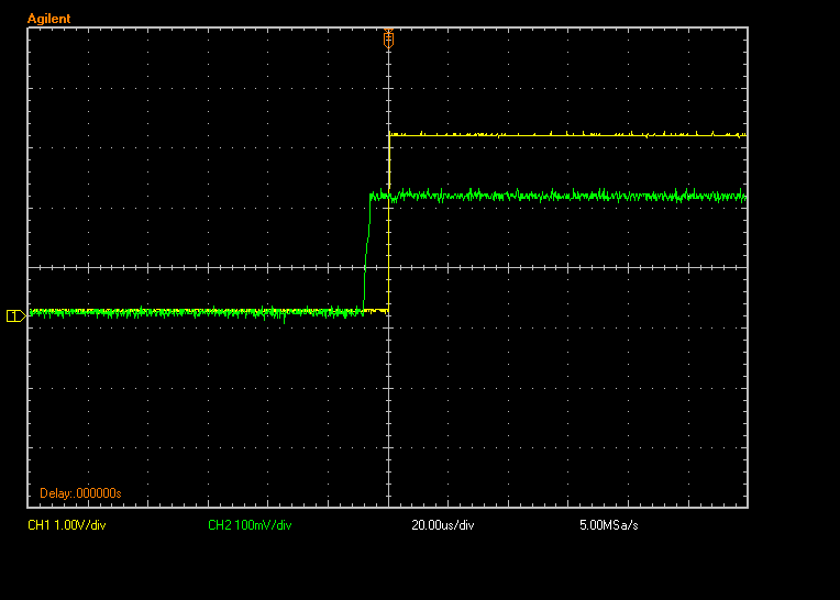
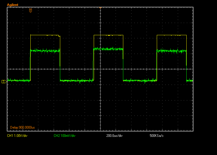
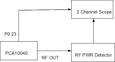
We are developing a beacon device with 10dBm power amplifier. During software development we noticed the control signals provided by ble_common_opt_pa_lna_t align poorly with the actual RF burst of the advertising beacon. We used a PCA10040 and measured RF output directly from the nRF52832. The amplifier control signal was routed out P0.23. In the bmp files below from the scope the measured RF power (shown in green) starts nearly 10usec ahead of the pa control signal from PPI. During testing with an actual external amplifier this results in significant loss of the advertising signal. The code (shown below) was a direct copy from your example in the blogs.
In general a power amplifier should have at least 1usec of turn on time ahead of the RF burst. Given the jitter and latency associated with your implementation on the PPI bus, 5 usec of advance notice would be useful. We are using S132 2.0.0-8 on nRF52832-QFAA-BA. Please advise how this can be resolved.
static void pa_lna_assist(void) { ret_code_t err_code;
static const uint32_t gpio_toggle_ch = 0;
static const uint32_t ppi_set_ch = 0;
static const uint32_t ppi_clr_ch = 1;

// Configure SoftDevice PA/LNA assist
ble_opt_t opt;
memset(&opt, 0, sizeof(ble_opt_t));
// Common PA/LNA config
opt.common_opt.pa_lna.gpiote_ch_id  = gpio_toggle_ch;        // GPIOTE channel
opt.common_opt.pa_lna.ppi_ch_id_set = ppi_set_ch;            // PPI channel for pin clearing
opt.common_opt.pa_lna.ppi_ch_id_clr = ppi_clr_ch;            // PPI channel for pin setting
// PA config
opt.common_opt.pa_lna.pa_cfg.active_high = 1;                // Set the pin to be active high
opt.common_opt.pa_lna.pa_cfg.enable      = 1;                // Enable toggling
opt.common_opt.pa_lna.pa_cfg.gpio_pin    = 23;      // The GPIO pin to toggle

// LNA config
opt.common_opt.pa_lna.lna_cfg.active_high  = 1;              // Set the pin to be active high
opt.common_opt.pa_lna.lna_cfg.enable       = 1;              // Enable toggling
opt.common_opt.pa_lna.lna_cfg.gpio_pin     = 22;   // The GPIO pin to toggle

NRF_GPIO->DIRSET = PA_MASK;
err_code = sd_ble_opt_set(BLE_COMMON_OPT_PA_LNA, &opt);
APP_ERROR_CHECK(err_code);
}
