nPM1300 HARDWARE

Hi Nordic:

       I use the nPM1300 to power the NRF5283 and external sensors. The nPM circuit schematic is as followsPlease check for any unreasonable parts.


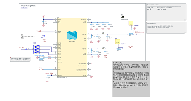
1 Charge and power the system. When a USB is inserted, 
  notify the main controller via I2C that charging has started and obtain battery level information, 
  then control the LED color accordingly.

2 There is no NTC resistor on the battery side. 
  An attempt is made to add an NTC resistor on the main control board to measure the system temperature (system overall power consumption is about 1mA, 
  with no additional heat generation apart from charging). Question: Can this NTC be used to measure the battery level?

3 The I2C bus is also connected in parallel with external sensors, 
  pulled up to the main controller voltage via 4.7kΩ resistors.。

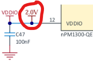
4  The GPIO pins of the nPM1300 are not used. Is it necessary to supply power to VDDIO?

BEST REGARDS!!

JERMI.JIN

20260424

  • Hi Jermi,

    Here are the observations for the schematics:

    1. VBUS nominal capacitance recommended is 1uF.

    2. VBAT needs to be connected to a 2.2uF bypass capacitor.

    3. For the SDA/SCL pins, if they are not used, connect to GND or VDDIO. Else, connect to VDDIO via pull-up resistors.

    4. Could you tell me why you have an additional 2.0V here:

    5. At the VBUSOUT pin, you need to have a 1uF decoupling capacitor here, even if it's not used.

    6. For VINLDO1 & VINLDO2, connect to the supply for switch/LDO and connect to GND if not used.

    7. The same for VOUTLDOx . i.e. connect to output capacitor if used, else connect them to ground.

    8. Also, this is how the VOUT1 and VOUT2 is connected to the supply:

    But I am not sure I see this in your schematic.

    Can this NTC be used to measure the battery level?

    I don't think that's possible because NTC is used to measure the temperature. And this cannot reliably tell you how much battery energy is left.

    The GPIO pins of the nPM1300 are not used. Is it necessary to supply power to VDDIO?

    The GPIO of the nPM is not used, but you do use TWI (I2C) on the main controller and since the TWI pins are on the same bus as the external sensors, the chip does need the VDDIO as the I/O voltage level.

    So this VDDIO basically tell the nPM chip what voltage the I2C buses are.

    I would suggest you to take a look at the nPM1300 Design Checklist, nPM1300 Hardware Design Guidelines and also the reference circuitry to properly and correctly proceed with the designing.

    Regards,

    Priyanka

Related