Problems implementing a one-to-many positioning system using Bluetooth CS on nRF54L15

I am developing an indoor positioning system using Bluetooth Channel Sounding (CS) on nRF Connect SDK v3.1.1. My setup involves one Initiator and four Reflectors.

Implementation Detail: To achieve real-time positioning, I have implemented a one-to-many architecture where the Initiator maintains four concurrent ACL connections simultaneously, performing CS procedures with each Reflector.

The Problem: In this concurrent 1-to-4 setup, I observe a high frequency of NaN values for IFFT and PBR results as soon as the distance exceeds 3 meters. However, using the official one-to-one CS sample from Nordic's GitHub on the same hardware, I can achieve stable and accurate ranging beyond 10 meters.

Observations on Antenna & Orientation: I have attempted to manually align the PCB antennas of the nRF54L15 DKs. While this slightly mitigates the issue, it does not solve the underlying problem. In our target application, the Initiator is mobile, making manual orientation adjustment impossible.

Technical Data: I am currently logging the phase difference and ToF (Time of Flight) for each channel to analyze why the PBR/RTT engine is failing to converge in this concurrent environment.

Questions:

  1. Does maintaining four concurrent CS-enabled connections impose specific constraints on radio scheduling that could lead to incomplete IQ sampling or IFFT failures (NaN) at relatively short distances?

  2. Are there recommended subevent_len, subevent_interval, or event_interval settings specifically optimized for multi-link concurrent CS to avoid radio resource contention?

  3. How does the CS engine handle Link Layer priority when multiple CS procedures overlap in the time domain? Could this be the reason why the performance is significantly worse than the 1-to-1 sample?

  4. Are there any best practices for improving signal robustness in a multi-reflector environment where antenna polarization and multipath cannot be controlled?
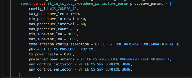
    For further reference, I’ve included the hci_ipc folder and the project’s prj.conf. The attached image displays the specific CS configuration settings used in main.c."
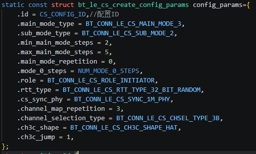
    prj_hci_ipc.conf87253.prj.conf

  • Hello,

    For clarity, how is prj_hci_ipc.conf included in your project? And what is it's location (in your application folder)?

    Channel sounding is a techonlogy that doesn't scale incredible well, but it should be possible to handle 4 connections, but perhaps not with the frequency that you imagined. 

    1: It does require more time, and more CPU processing power. Exactly if this is the reason why you see NaN in your log, I am not sure. You can try to figure it out through debugging. You should be able to detect why it decides to print NaN instead of a number. Perhaps you can share the piece of code that prints it, and I can help you do some digging to see if I can figure out why.

    2: We have some recommendations here: https://docs.nordicsemi.com/bundle/ncs-latest/page/nrfxlib/softdevice_controller/doc/scheduling.html#channel_sounding_timing

    3/4: These are not trivial questions. But first, what kind of devices do you plan on making? Let us, for simplicity, call the 4 stationary (I assume you have 4 stationary devices, and one moving device, based on what you write) devices for scanners, and the moving device for the tag.

    Where do you want your CS (Channel Sounding) data to end up? Do you want it on the tag, or does it end up in a computer somewhere? And how do you transfer it from the tag to where it is being used? The reason I ask is that if you need the data outside the tag itself, then perhaps you should consider having the scanners do the CS initiator role, and the tag can be the reflector. Another effect of this is that the main number crunching happens at the initiator side of the connection. Because of this, there are two reasons you might want to switch up the roles:

    1: The stationary scanners tend to have better battery capacity, and besides they will only do 1/4th of the number crunching, compared to the tag being the initiator and calculating the distance to 4 reflectors. 

    2: You will spread out the load of calculations, so that instead of one device having to do calculations for 4 distances, you will have 4 devices each doing calculations for 1 distance. It is simply cutting down the processing time by 4.

    BUT: You will have to transfer the distance data to a centralized location if you intend to map out where the tag is located.

    One thing to keep in mind: If you decide to switch around the roles, it is still recommended to have the tag act as the BLE central in the connections. This is because then it will be in control of the connections, avoiding collissions. So if you want to test this, the first would be to flip around the BLE role in the sample, so that the central will be the reflector, and the peripheral will be the initiator.

    Best regards,

    Edvin

Related