nrf54: (Ab)using SPIM as a shift-register - between-TXLIST latency

Hi

I'm trying to drive a 75hc595-type shift register with a SPIM instance on the nrf54l15.

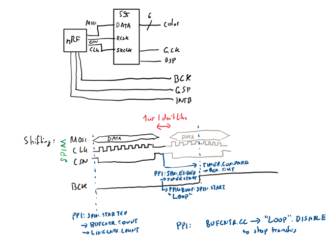
I connect MOSI to the shift register data input, CLK to the shift register clock, and CSN to the output-stage-enable register (i.e. latch from the input shifter to the output). I use the maximum frequency of the SPIM22, namely a prescaler of 2, to reach 8MHz on the output, aiming for 1 MHz output on the shift register. To set the outputs, I use EasyDMA in List mode with a MAXCNT of 1. Using CSNPOL Low, CSN is driven HIGH at the end of the transfer, thus sampling automatically into the shift register. I set IFTIMING.CSNDUR to 0.

Because I have a fixed number of bytes to sample (~240), I use a TIMER22 as a byte-counter, and a PPI group in DPPI20. I link the SPI ENDED event to the SPI STARTED event in one PPI channel, which I add to a PPIGROUP, and into the TIMER22 COUNT event. I then program a CC to the maximum number of bytes, and link it in another PPI channel to the PPIGROUP DISABLE task to break the loop and stop transferring after the programmed number of bytes.

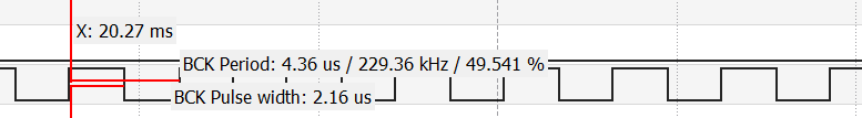
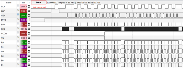
I was expecting _some_ delay caused by the CSN and rearming. But I'm observing >1us of delay between clock pulse sequences (i.e. SPI transfer active), resulting in an oscilloscope-measured time of 2us (instead of slightly more than 1us expected) between CSN pulses, halving the aimed-for frequency. Essentially, the bus idles for 1 us after every byte (which also takes 1us to transfer).

I'm a bit confused about these delays. I know that SHORTS.END_START is supposed to use IFTIMING.CSNDUR as a delay in peripheral clock cycles, so this should be 1/16 us (or 1/8 us) - not a full microsecond, so the peripheral is supposed to be faster. From what I understand from the documentation, the counter is also counting with a max delay of 1 from the PCLK, which is also 16MHz - but what I'm seeing looks like a clock of 1 MHz dominating the results.

Could you kindly point me to my mistake? I'm thinking about using the DMA TX END (rather than the SPI END) event to queue the next transfer, but I'm a bit hesitant regarding the safety of such a hack. Would the timings guarantee that the latency is enough to trigger only after the ENDED event? What would happen if the START task is triggered before (or in the same cycle where) the SPI ENDED event fires?

Is there another, better way? I was thinking about using the SPIM to transfer one array of 240 bytes at once, and pulsing the shift-latch using a different timer, but I'm a bit weary about the ultra-tight and hard-to-debug timing requirements caused by this approach given that my understanding of the PPI latencies already seems to be off.

Parents
  • Hi,


    Do you have any measurements to share, so I can see the delay? I would expect 1 us typically, based on the description in the datasheet.


    The time from .START -> actual transmission start is typically 1 us:

    https://docs.nordicsemi.com/bundle/ps_nrf54L15/page/_tmp/nrf54l15/autodita/SPIM/parameters.elec_spec.html

    And when .PSEL.CSN is configured, the timing will behave as described in the datasheet:

    https://docs.nordicsemi.com/bundle/ps_nrf54L15/page/spim.html#ariaid-title4


    Ie. you will get a delay before- and after a transmission, thus you will see a "double delay" between each transaction (one byte in your scenario).

    I set IFTIMING.CSNDUR to 0.

    If we look at the definition of this register:

    https://docs.nordicsemi.com/bundle/ps_nrf54L15/page/spim.html#ariaid-title59

    it mentions specifically:

    Note that for low values of CSNDUR, the system turnaround time will dominate the actual time between transactions


    Kind regards,

    Håkon

  • Hi

    I apologize for the delay.
    Unfortunately, I currently only have access to the capture of a pin (BCK) toggled at a fixed delay after the SPI end. This is expected to read ~1us for every transaction when considering the raw transmission time.

    Your mention of the 1us START delay explains the other 1us of delay between the transfers.

    I find the datasheet a bit confusing regarding the CSNDUR, especially because the timing diagram in Figure 4 does not actually include this "turnaround" time. Is the time of "CSN high" a function of min(1us, CSNDUR*(1/PCLK))? Or 1us + CSNDUR*(1/PLK)? And does this 1us START delay apply also with SHORTS.ENDED_START ?

    Considering my usecase, would it be possible to PPI a pin to pulse the "CSN" pin (then disconnected from the SPI) precisely after the last bit has been asserted and the CLK has sampled? Specifically, is the SHORT on the TIMER clear constant in time, and is the peripheral clock of one domain synched?
    Or is there a "best practice" to implement the SRCLK signal on a 595-type IC in sync with the SPI peripheral?

    Kind regards

Reply
  • Hi

    I apologize for the delay.
    Unfortunately, I currently only have access to the capture of a pin (BCK) toggled at a fixed delay after the SPI end. This is expected to read ~1us for every transaction when considering the raw transmission time.

    Your mention of the 1us START delay explains the other 1us of delay between the transfers.

    I find the datasheet a bit confusing regarding the CSNDUR, especially because the timing diagram in Figure 4 does not actually include this "turnaround" time. Is the time of "CSN high" a function of min(1us, CSNDUR*(1/PCLK))? Or 1us + CSNDUR*(1/PLK)? And does this 1us START delay apply also with SHORTS.ENDED_START ?

    Considering my usecase, would it be possible to PPI a pin to pulse the "CSN" pin (then disconnected from the SPI) precisely after the last bit has been asserted and the CLK has sampled? Specifically, is the SHORT on the TIMER clear constant in time, and is the peripheral clock of one domain synched?
    Or is there a "best practice" to implement the SRCLK signal on a 595-type IC in sync with the SPI peripheral?

    Kind regards

Children
No Data
Related